CAN Analyzer
The CAN Analyzer in the AutoPi Cloud is an interactive tool for discovering, testing, and validating CAN bus communication on a connected vehicle or machine. It provides a UI-based interface for running low-level CAN/OBD commands, monitoring raw traffic, and validating protocol configurations before deploying loggers or integrations.
This tool is primarily used during initial setup, troubleshooting, reverse engineering, and integration validation.
Overview
The CAN Analyzer enables:
- Passive listening of CAN traffic (sniffing)
- Testing different CAN protocols and baud rates
- Sending diagnostic requests (PID / UDS / J1939)
- Recording and replaying CAN messages
- Verifying communication between AutoPi and ECU(s)
It acts as a real-time inspection layer between the AutoPi device and the vehicle network.
Interface Structure
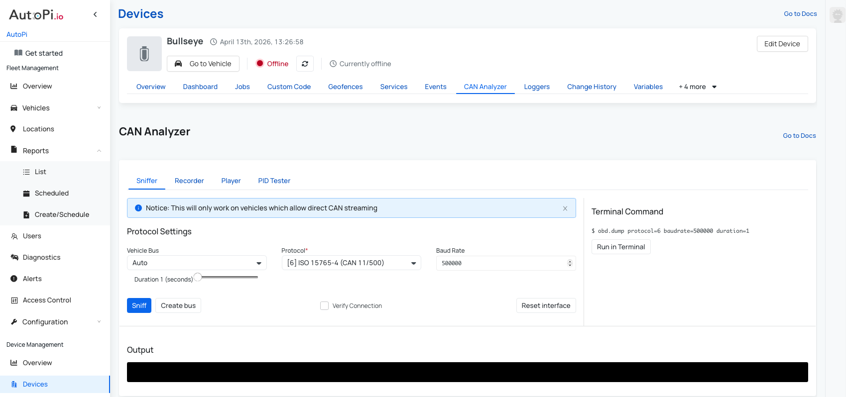
The CAN Analyzer page consists of four main tabs:
- Sniffer - passive monitoring of CAN traffic.
- Recorder - captures CAN messages and stores them for later use.
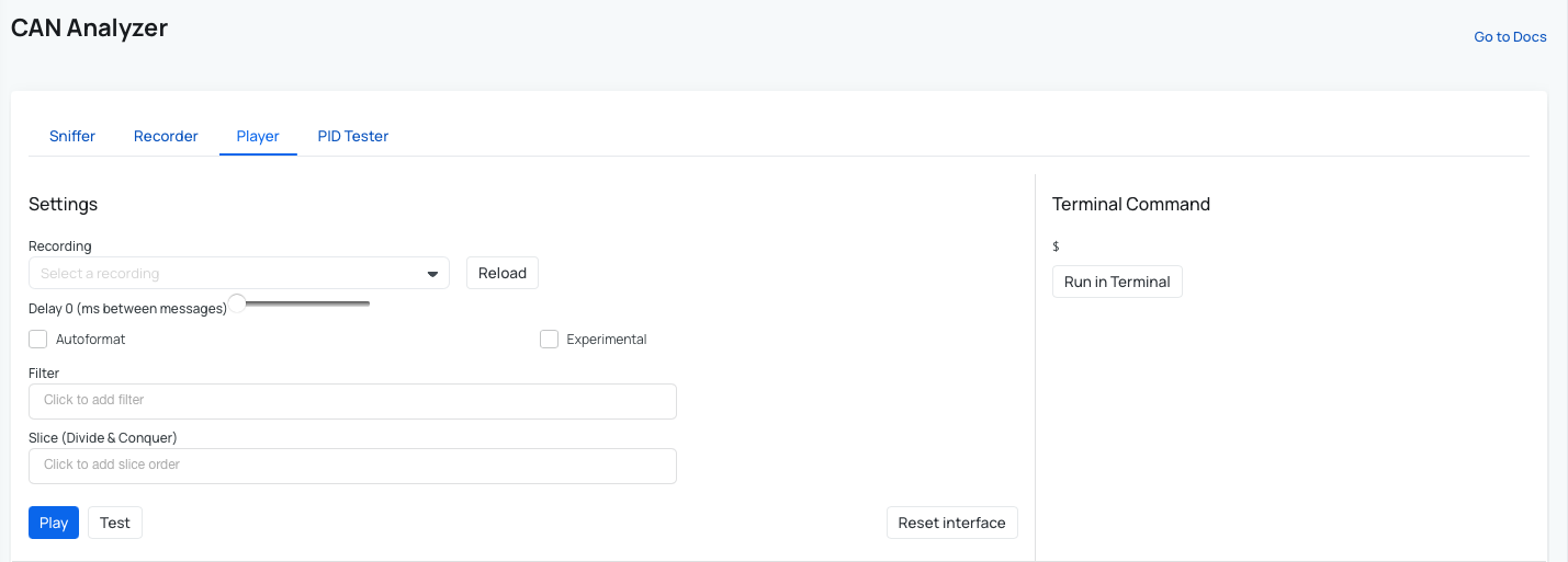
- Player - replays previously recorded CAN traffic.
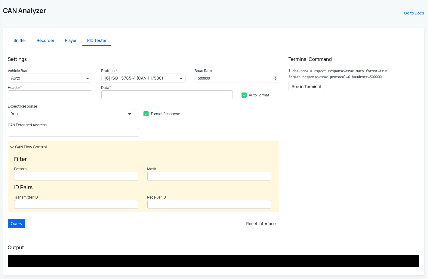
- PID Tester - sends request-response queries to ECUs.
Sniffer (Passive CAN Monitoring)
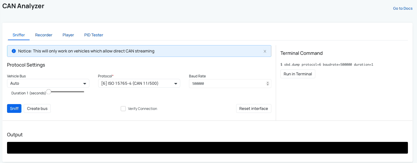
Note: This will only work on vehicles which allow direct CAN streaming.
Purpose
Used to detect:
- Active CAN bus.
- Correct protocol and baud rate.
- Raw CAN messages.
How it works
The sniffer runs a passive monitor similar to:
obd.monitor duration=5 protocol=<protocol> baudrate=<baudrate>
This listens to all CAN frames being broadcast on the bus. This is required because:
- Some vehicles stream data continuously.
- Others only respond to requests (PIDs).
Configuration
| Field | Description |
|---|---|
| Vehicle Bus | Select CAN interface (auto or manual) |
| Protocol | CAN protocol (e.g. ISO 15765-4, J1939) |
| Baud Rate | Typical values: 125k, 250k, 500k |
| Duration | Capture time in seconds |
Workflow
- Start with
AutoVehicle Bus or a known protocol. - Click Sniff.
- Observe output:
- No data → wrong configuration.
- Data present → valid configuration.
- If you didn't receive any data in the output field, adjust the protocol and/or baud rate until consistent data is received.
- You can also use
Verify Connectionwhen an obd request is sent to the vehicle and device awaits for the response, as a second layer of verification of the correct connection setup. - Create bus, if you are sure of a Vehicle Bus used by your vehicle.
This process is essential when:
- Vehicle protocol is unknown. You can read more here: Setting up CAN Bus Protocol.
- Working with heavy-duty (J1939) or proprietary buses. You can read more here: Heavy Duty Vehicles/ J1939 Protocol.
Recorder
Purpose
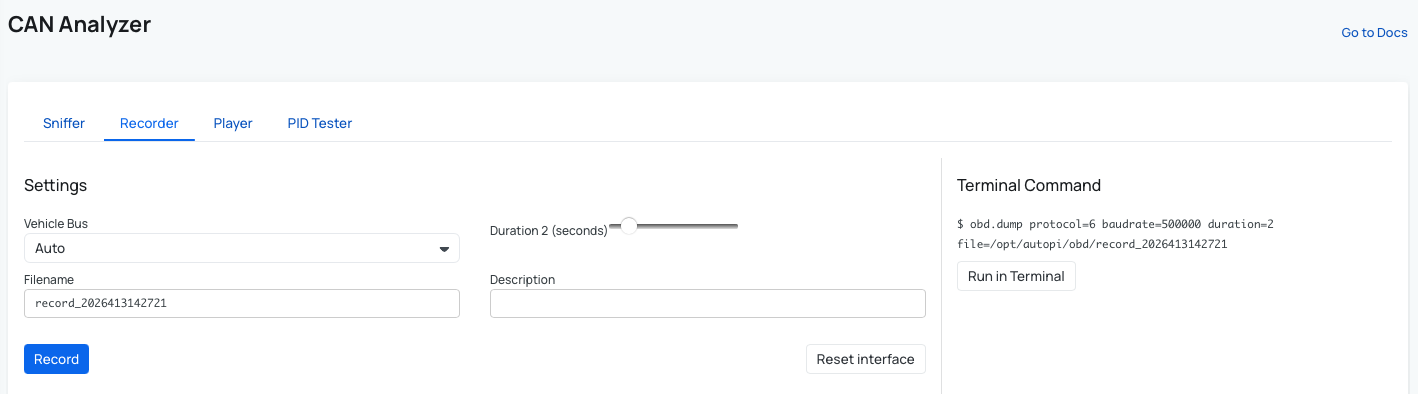
Stores CAN traffic for:
- Offline analysis
- Debugging intermittent issues
- Sharing datasets
Backend equivalent:
can.dump duration=10 file=test.log
This captures raw CAN frames to files such as .log, .csv, or .blf
Player
Purpose
Replays recorded CAN data onto the bus.
Use cases
- Simulate ECU behavior
- Test integrations without a live vehicle
- Reproduce issues from recorded sessions
PID Tester (Active Requests)
Purpose
Send request-response messages to ECUs.
Example:
obd.query rpm mode=01 pid=0C
This requests engine RPM from the ECU.
When to use
Use PID Tester when:
- Data is not broadcast automatically.
- Specific signals are required.
- Validating diagnostic communication.
Terminal Integration
All actions in the CAN Analyzer correspond to terminal commands.
Example:
obd.dump protocol=6 baudrate=500000 duration=1
This allows:
- Reproducibility.
- Automation via scripts.
- Debugging outside the UI.
Typical Use Cases
-
Protocol Detection - identify correct CAN configuration by testing:
- Protocol.
- Baud rate.
-
Vehicle Integration - verify that:
- AutoPi can access CAN data.
- ECUs respond correctly.
-
Reverse Engineering - analyze unknown CAN signals by:
- Sniffing traffic.
- Correlating values with real-world behavior.
-
Troubleshooting - detect issues such as:
- No CAN traffic.
- Incorrect wiring.
- Unsupported protocol.
-
Development & Testing:
- Validate CAN-based applications.
- Simulate environments using Player.
Summary
The CAN Analyzer is a diagnostic and validation tool that sits between raw CAN access and production logging. It allows you to:
- Discover how a vehicle communicates
- Validate configurations before deployment
- Debug issues at the lowest level
- Build reliable CAN-based solutions on top of AutoPi
It is typically the first step in any CAN integration workflow.
Important Notes
- Requires vehicle support for CAN access (OBD or direct wiring)
- Ignition needs to be ON
- Some vehicles require wake-up communication
- Avoid testing on moving vehicles
Best Practice Workflow
- Ensure device is powered on and online
- Start with Sniffer:
- Test common baud rates (250k / 500k)
- Identify working configuration
- Use PID Tester to validate responses
- Record traffic if needed
- Build loggers or integrations based on findings
 Shop AutoPi devices
 Compare devices
 Contact sales
 Contact support