Upgrade/Replace Your Raspberry Pi Computer
This guide will walk you through safely disassembling your AutoPi device, removing and replacing the Raspberry Pi computer, and reassembling everything with proper cable connections. The guide includes detailed step-by-step instructions with visual references for both disassembly and assembly, plus essential post-upgrade steps for registering your new device in AutoPi Cloud.
Upgrading or replacing your Raspberry Pi is a delicate process that requires careful handling of internal cables and connectors. Read this guide completely before beginning to ensure you understand how all components fit together and to avoid damaging cables or connections.
What you'll accomplish:
- Safely disassemble your AutoPi device.
- Remove the existing Raspberry Pi and disconnect all cables.
- Install a new Raspberry Pi computer.
- Properly reconnect all internal cables and antennas.
- Reassemble the device enclosure.
- Register the new device in AutoPi Cloud.
Please read the entire guide to understand how all the components fit together. Be especially careful not to tear or damage cables when handling the device casing or removing internal components. When in doubt, refer to the visual guides provided for each step.
Disassembling the AutoPi Device
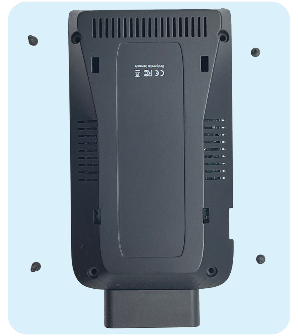
Step 1: On the bottom side of the device, remove the screws that hold the casing in place.
Step 2: Open the bottom casing on the side, just like a book. Be careful when doing this as there is a cable connection between the modem and the casing.
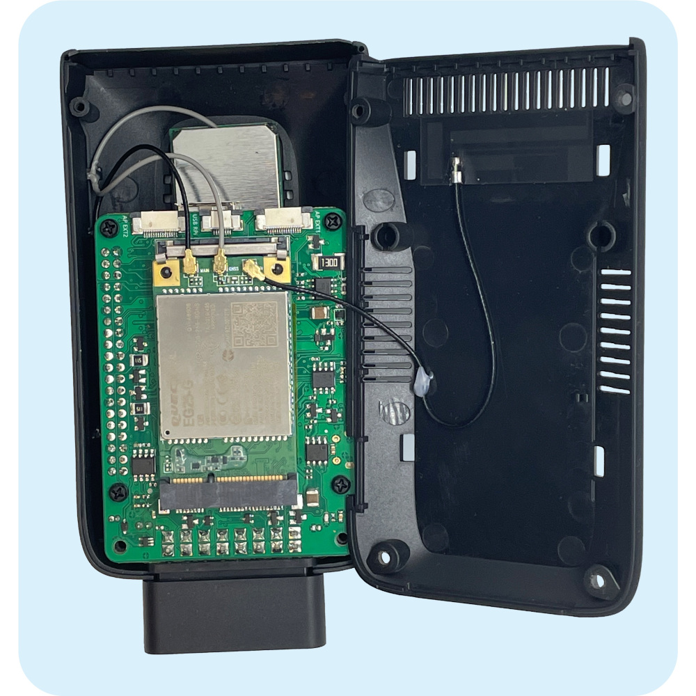
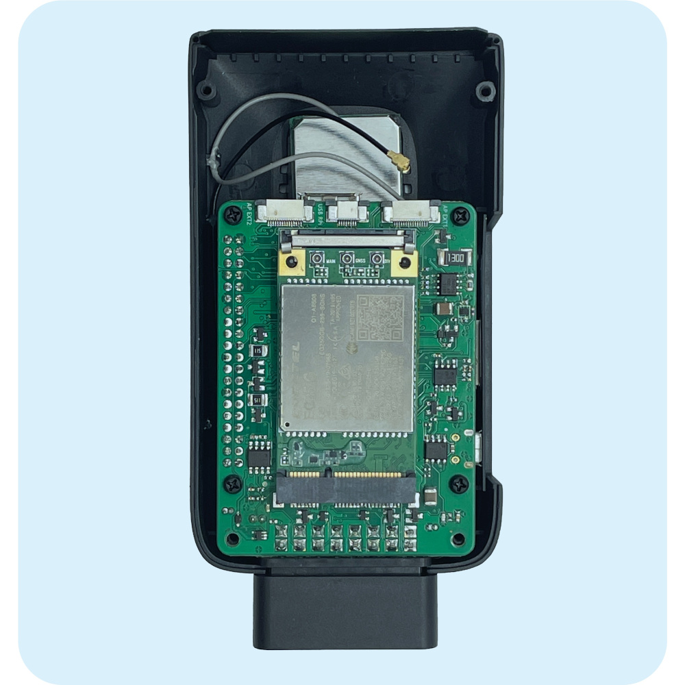
Step 3: Remove all three cable connections from the modem module. The cables need to be pulled up to be removed from their sockets. There are two black cables on each side and one gray cable in the middle. We suggest using a pair of pliers to help you with this.
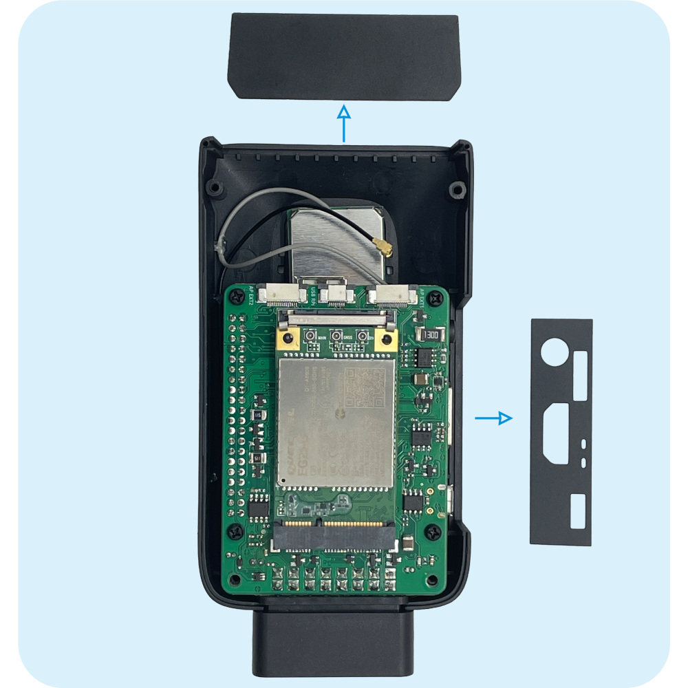
Step 4: Remove both shields from the back and the side. They just need to be slid up.
Note: At the front of the device, there is a plastic OBD connector. In the next step, you will need to grab the OBD connector and pull it up from the top casing.
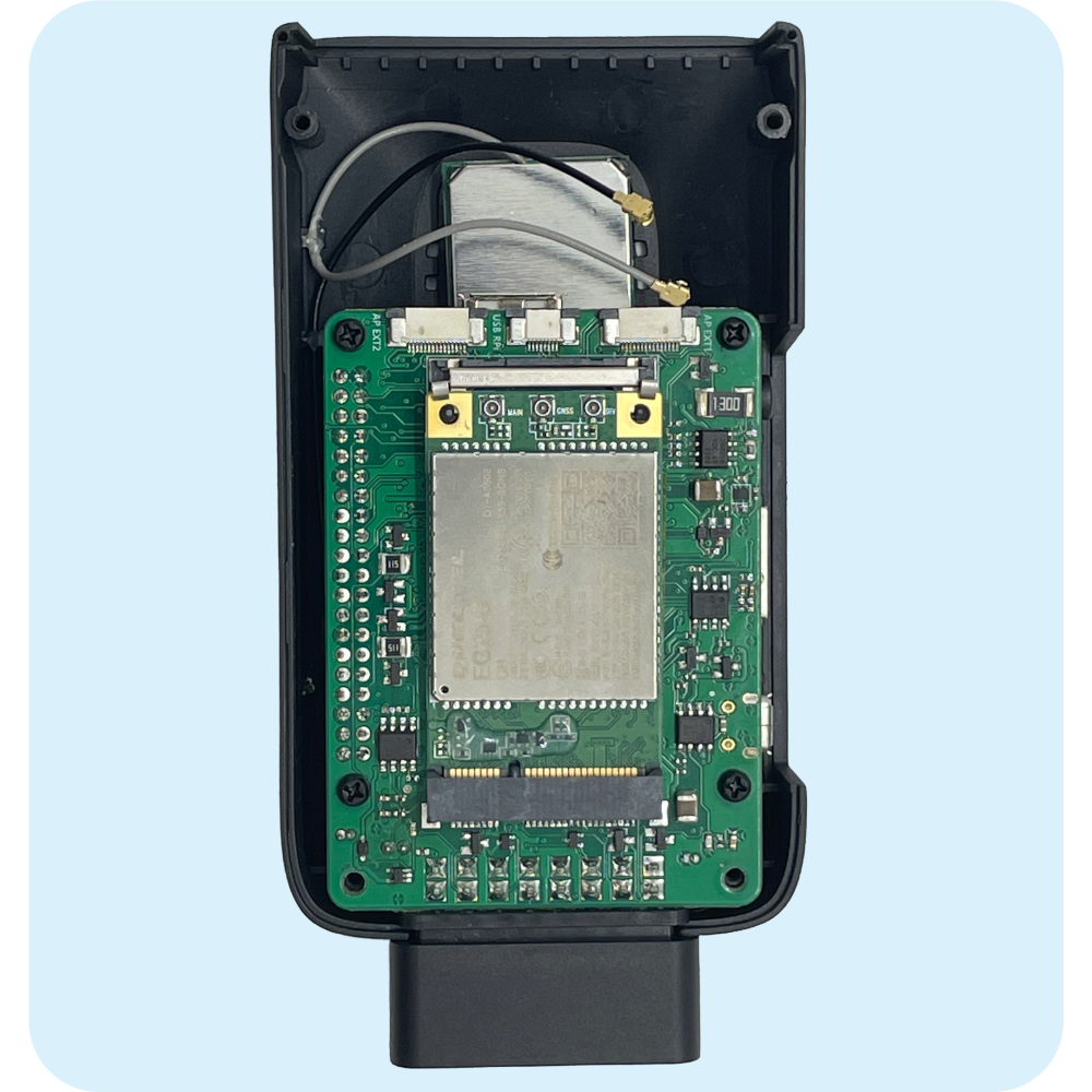
Step 5: Slowly pull up the board by the OBD connector. Beneath, you will find a speaker and a yellow battery attached to the top casing. You will need to remove the cables of those two components from the board. To remove the cables, simply pull them out of their sockets.
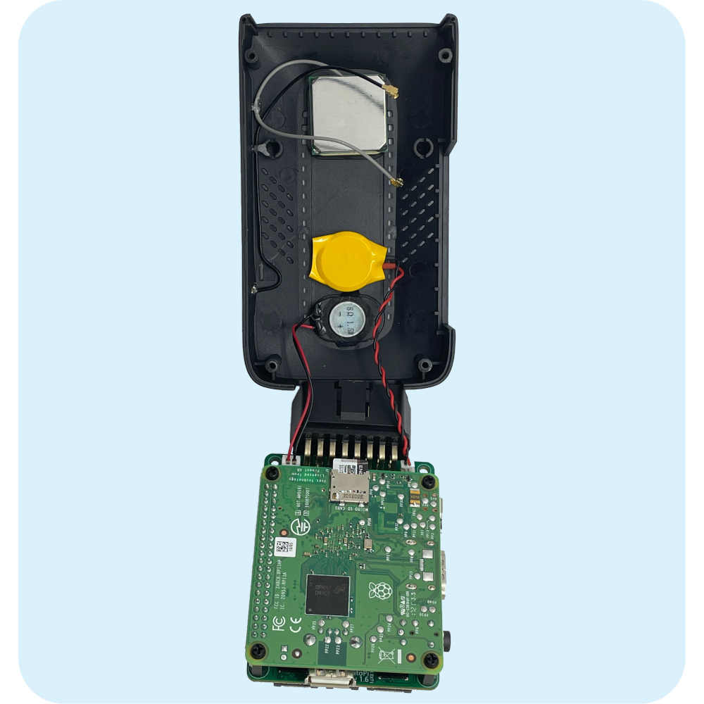
Note: Once detached from the battery and the speaker, your AutoPi device will look like this, with the modem facing upwards.
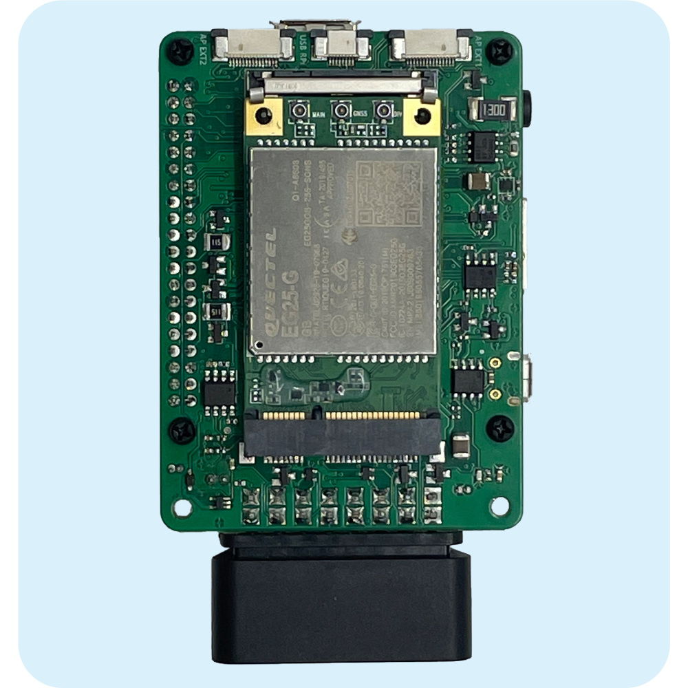
Step 6: Turn the board around to reveal the Raspberry Pi. You can also see the memory card from this side. Next, remove the plastic screws that secure the Raspberry. Disconnect the USB cable.
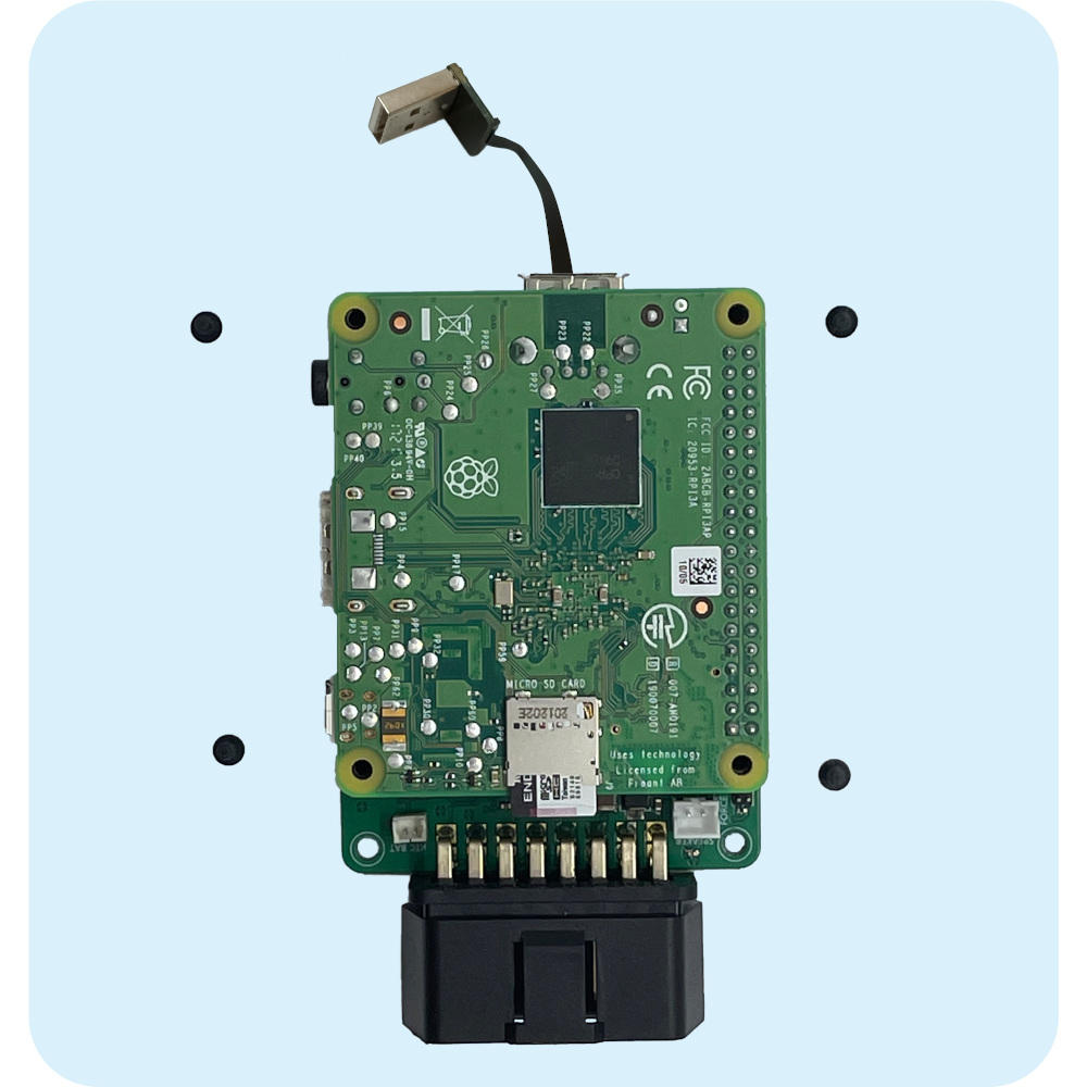
Step 7: Gently pull out the Raspberry Pi from the board. All the GPIO pins from the Raspberry Pi get connected to the sockets on the board. You should be able to get them out of their sockets by either pulling firmly, or wiggling left to right.
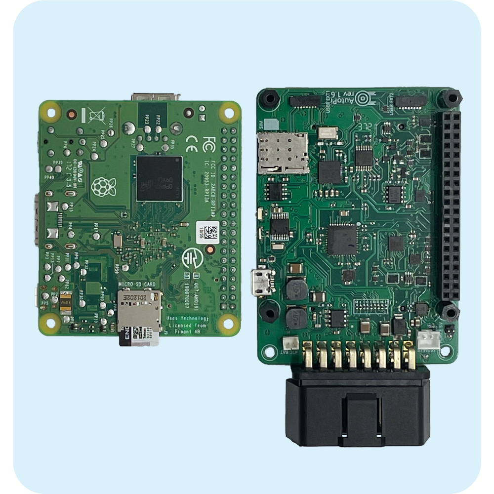
Assembling Back the AutoPi Device
Step 8: Grab your new Raspberry Pi board.
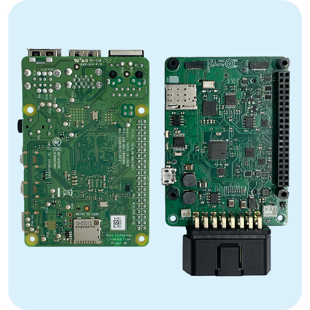
Step 9: Plug in your new Raspberry Pi into the board. The memory card slot should be facing the OBD connector. To plug in, simply align the GPIO pins with their respective sockets and push down.
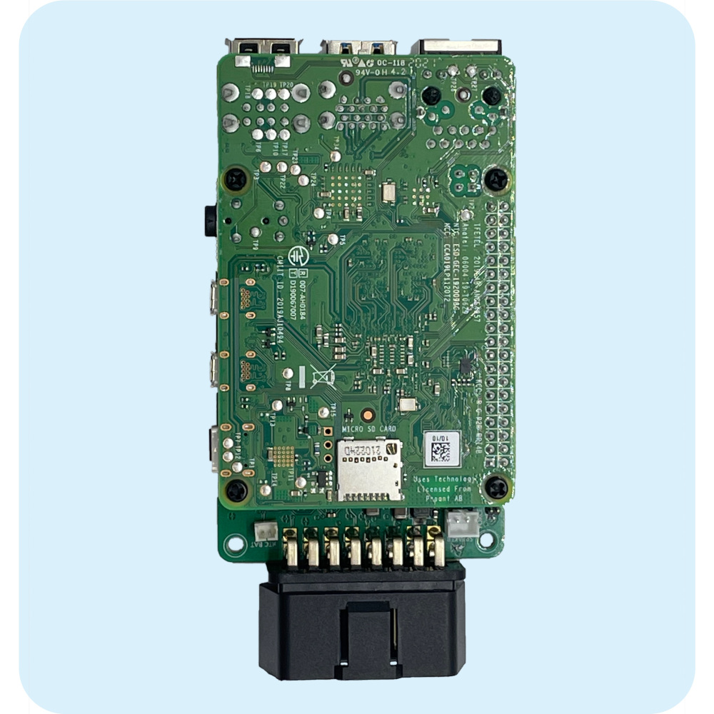
Step 10: Plug in the USB cable. Don’t forget to plug in your memory card as well.
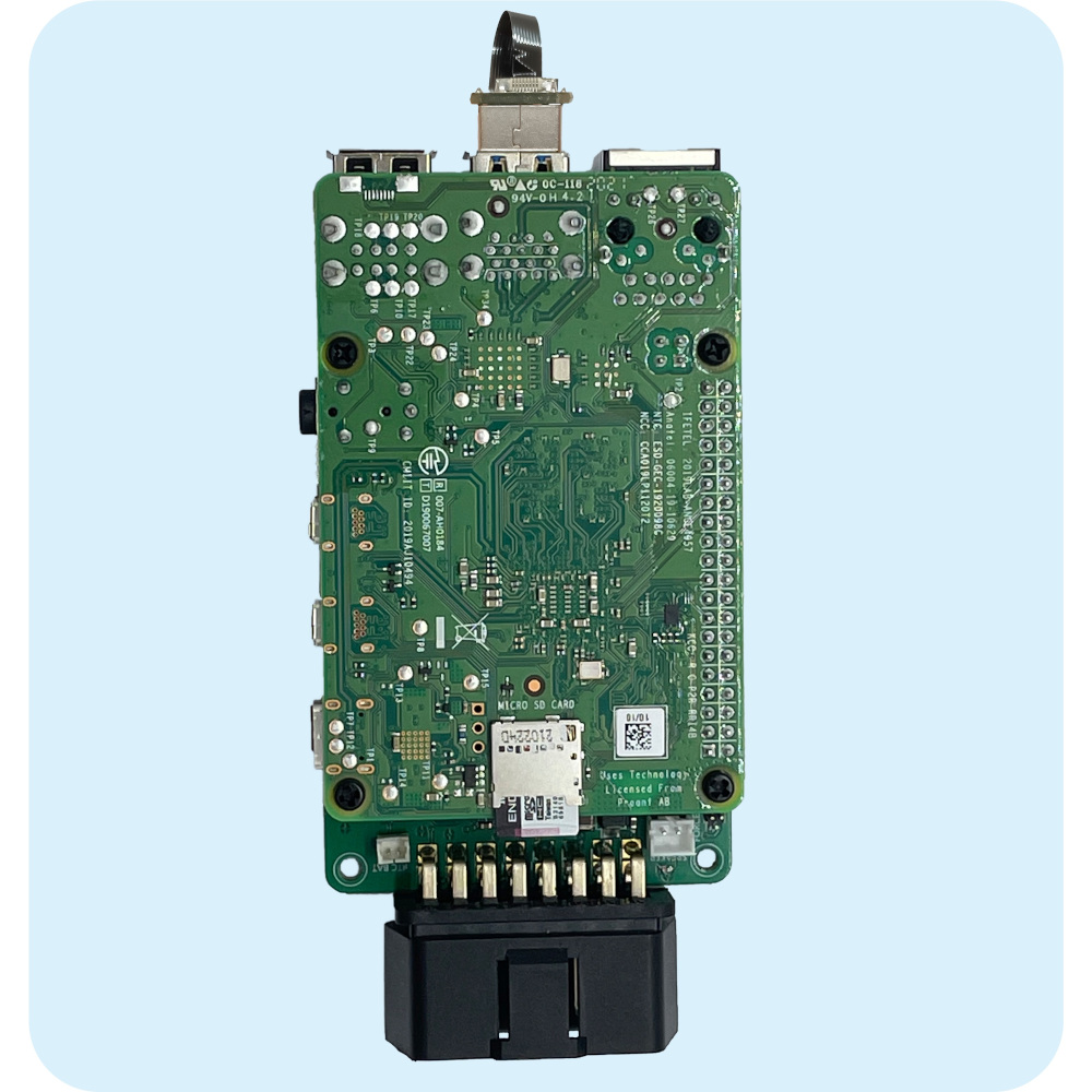
Step 11: Turn the device around and prepare the casing. You will need to connect the battery and the speaker cables first.
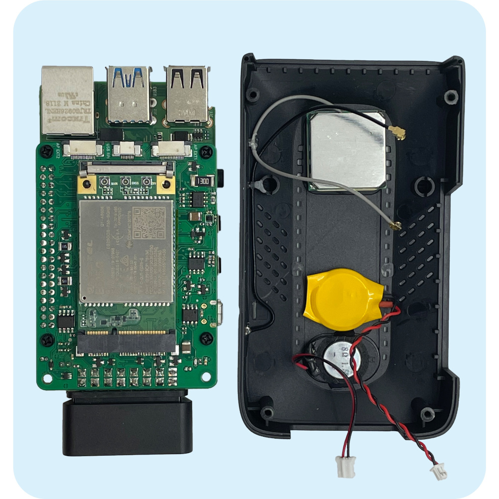
Step 12: Connect both cables to the board. The battery has a smaller connector, while the speaker has a bigger connector.
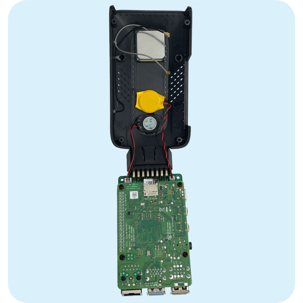
Note: The cables need to be connected like this. For both, the red cable always goes on the outside, the black cable goes on the inside.
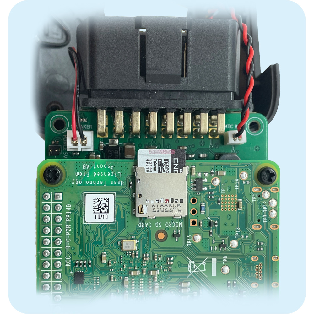
Step 13: Tuck both cables beneath the device and place it back into the casing like this. The OBD connector has a thin cutout along the plastic of where the casing needs to fit in. However, make sure that the black and gray cables are sticking out from the side, as you will need to connect them to the modem in the next step.
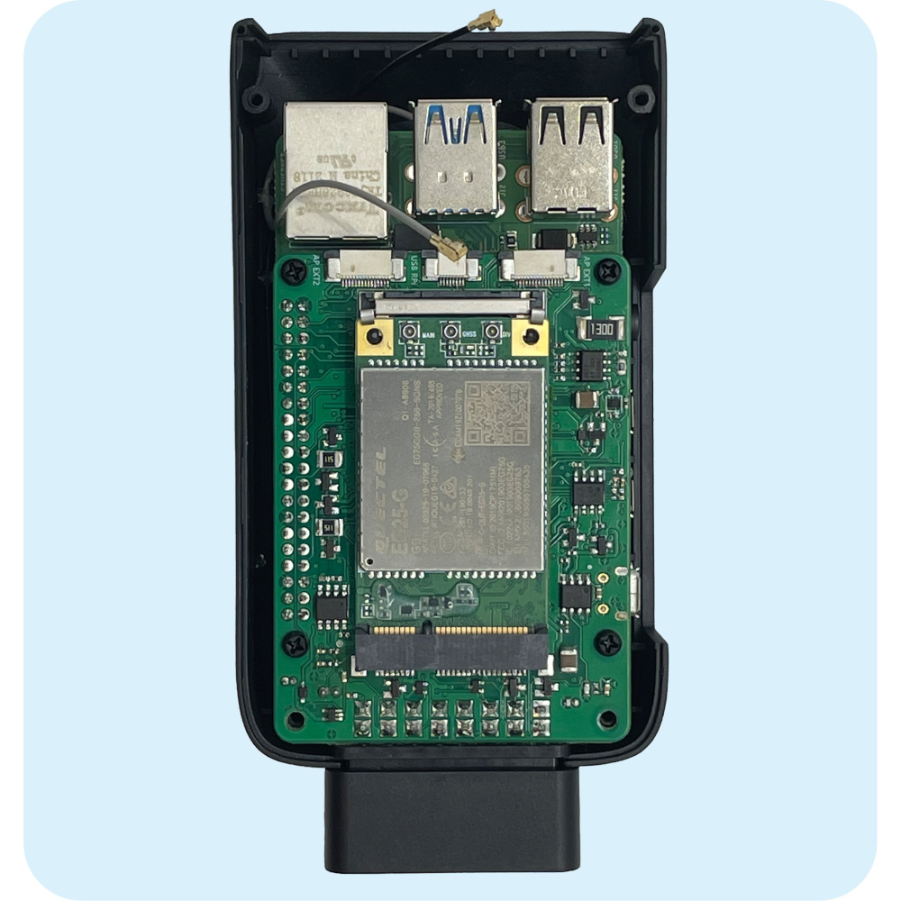
Step 14: Connect the antennas by placing them on their sockets and the firmly pushing down until you hear a click sound. The black cable goes on the side while the gray one goes in the middle. In addition, you will also need to slide down the back shield and the lateral shield.
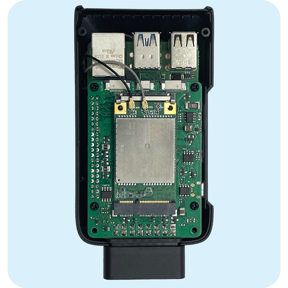
Step 15: Prepare the bottom casing and place it in the same position as when you took it out. You will then need to connect the black cable to the last remaining socket on the modem. Fold down the casing so the device completely seals.
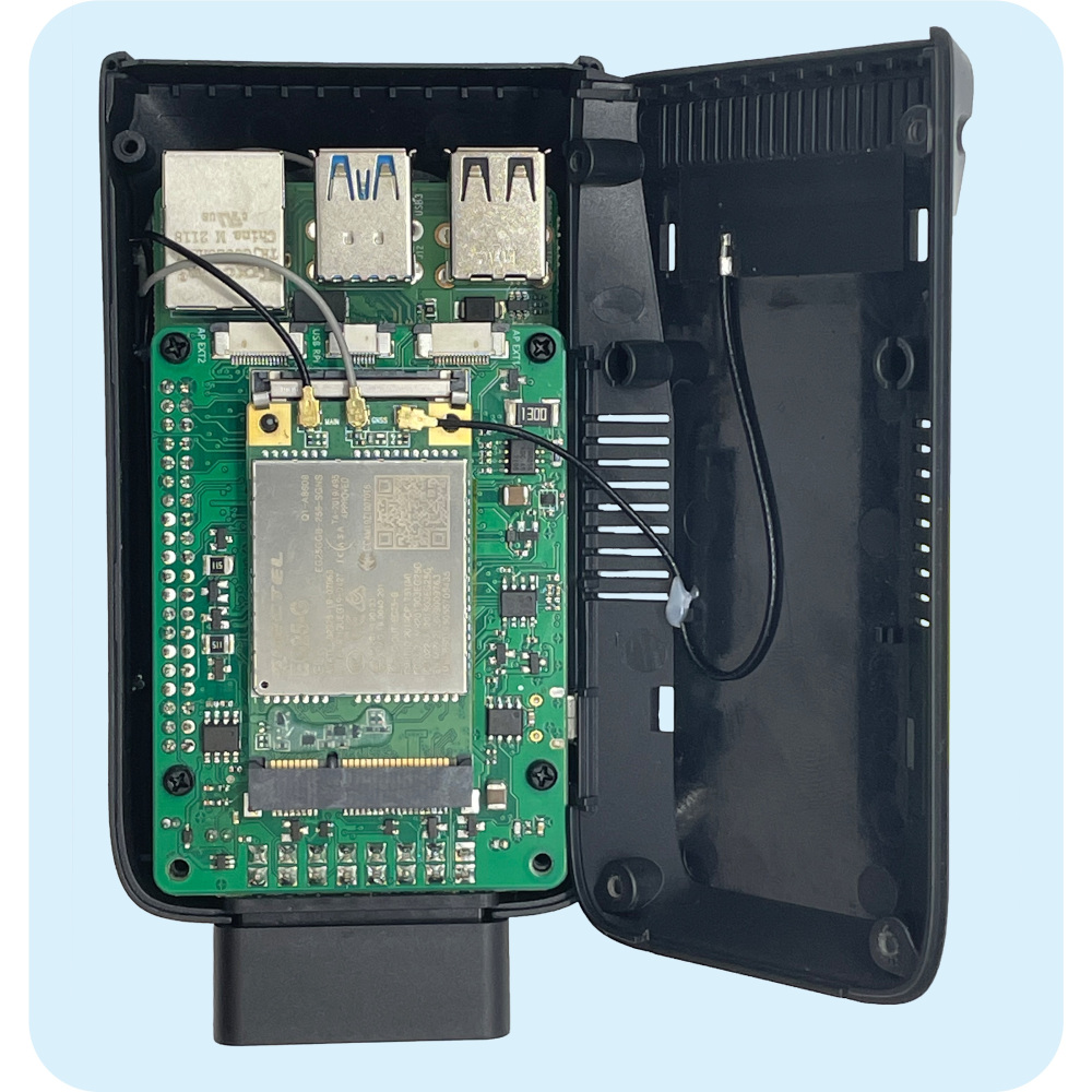
Step 16: Finally, screw back in the four metal screws that you took out in the beginning. You don’t have to worry about where to put them as they all have the same dimensions.
Step 17: When you replace or upgrade your Raspberry Pi, the device generates a new UNIT ID. This new ID must be updated on AutoPi’s system. Please contact our support team at support@autopi.io and provide both your new and old UNIT IDs (Unit ID is the ID sticker on the side of your device.).
Step 18: Once you receive confirmation from support that your UNIT ID has been updated, you’ll need to accept the new key in the cloud:
- Go to Device.
- Click the Settings icon (top right corner).
- Select: Accept Key.
Step 19: Finally, update your device to the latest software version:
- Navigate to the Software Updates tab.
- Click Update.
- Wait till your device sync all changes and double check in Software Updates tab if the state of your device shows as UPDATED.
Your device should now be fully operational!
 Shop AutoPi devices
 Compare devices
 Contact sales
 Contact support