Modbus Server
The AutoPi device can function as a Modbus server (slave), exposing vehicle data — including OBD-II readings, Diagnostic Trouble Codes (DTCs), and other logged values — as Modbus registers. Any standard Modbus client (such as a PLC, SCADA system, or HMI) can read these registers over TCP, UDP, or serial. This enables direct integration with industrial control systems, fleet monitoring platforms, and IoT applications without additional middleware.
Overview
What is Modbus?
Modbus is a widely-adopted, open-source industrial communication protocol designed for reliable supervisory control and data acquisition (SCADA). Originally developed for serial communication, Modbus has been extended to support TCP/IP networks. Key characteristics include:
- Simplicity — Easy to implement and integrate across diverse systems
- Standardization — Supported by thousands of industrial devices (PLCs, HMIs, sensors, gateways)
- Flexibility — Works over serial (RTU/ASCII), TCP, and UDP transports
- Scalability — Suitable for both small local systems and large remote deployments
When the AutoPi acts as a Modbus server, it makes vehicle data available using the standard Modbus register protocol, allowing existing industrial systems to consume real-time vehicle information.
Redis Cache on the AutoPi
Redis is an in-memory data store used internally by the AutoPi to cache real-time vehicle data. Here's how it works:
- Data Storage — Loggers (OBD, GPS, CAN, etc.) continuously write their data to Redis instead of a slow database
- Low Latency — In-memory storage ensures sub-millisecond read/write performance, critical for real-time vehicle monitoring
- TTL (Time-to-Live) — Each cached value automatically expires after a configurable duration (default: 60 seconds), ensuring fresh data is always served
- Returner Integration — The Modbus server reads directly from Redis cache when clients request data, providing immediate responses
This architecture decouples data collection from data delivery, allowing multiple applications (like Modbus, cloud APIs, and local services) to access the same live vehicle data without conflicts.
How It Works
- Loggers (e.g. OBD) run on the device and continuously write values to an internal cache.
- When a Modbus client requests a register, the Modbus server reads the corresponding value from that cache.
- You define which Modbus register address maps to which data field.
No polling is required from the client side — the device keeps the cache up to date based on the configured logger intervals.
Setup
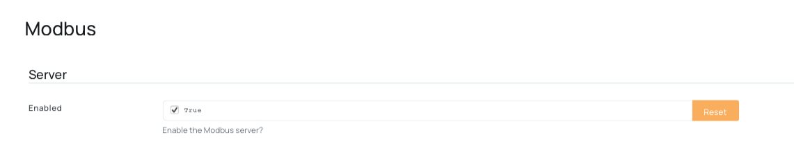
Step 1 — Enable the Modbus Server Engine
Navigate to Device → Advanced Settings → Modbus and enable the modbus_server engine.
Once enabled, the modbus_server will be available as a data returner for loggers. This means you can configure loggers to send their data directly to the Modbus server, where it will be stored in Redis cache.
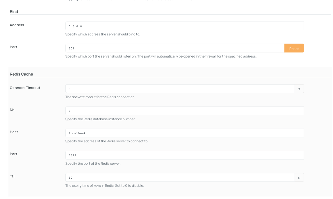
Optional Advanced Settings:
If needed, you can adjust additional parameters under the same settings:
- Bind — Configure the address and port for the Modbus server
- Redis Cache — Adjust connection timeout, database, host, and port settings
- TTL — Data retention time in Redis (default: 60 seconds). This ensures clients receive current data, not stale values.
Step 2 — Configure the Register Map
Navigate to Device → Advanced Settings → Modbus → Register Map. This is where you map Modbus register addresses to vehicle data fields from your loggers.
Default Registers
If no custom register map is configured, the following defaults apply:
- Register 0 → Engine RPM
- Register 1 → Vehicle speed
Field Reference:
| Field | Description |
|---|---|
register | Modbus register address (0-based) |
redis_key | Data field name from the logger |
default_value | Fallback value if data is unavailable (default: 0) |
All register values are stored as uint16 (range: 0–65535). Floating-point values are rounded automatically.
Adding Custom Registers
To expose additional data, add new register mappings:
-
Click Add New
-
Enter the mapping using this format:
Generic format:
{"register": <address>, "redis_key": "<data_field>", "default_value": <fallback_value>}Example (Engine RPM):
{"register": 0, "redis_key": "obd.rpm", "default_value": 0} -
Click Save
Important: Each register mapping can reference only one
redis_key. Ensure theredis_keymatches the logger's output field name exactly. Logger field names typically follow the formatobd.loggername(e.g.,obd.rpm,obd.speed). For multi-word logger names, use lowercase with no spaces.
Example on AutoPi Cloud
Below is an example of a complete register map with multiple signals configured. This demonstrates how to properly set up several common vehicle data points:
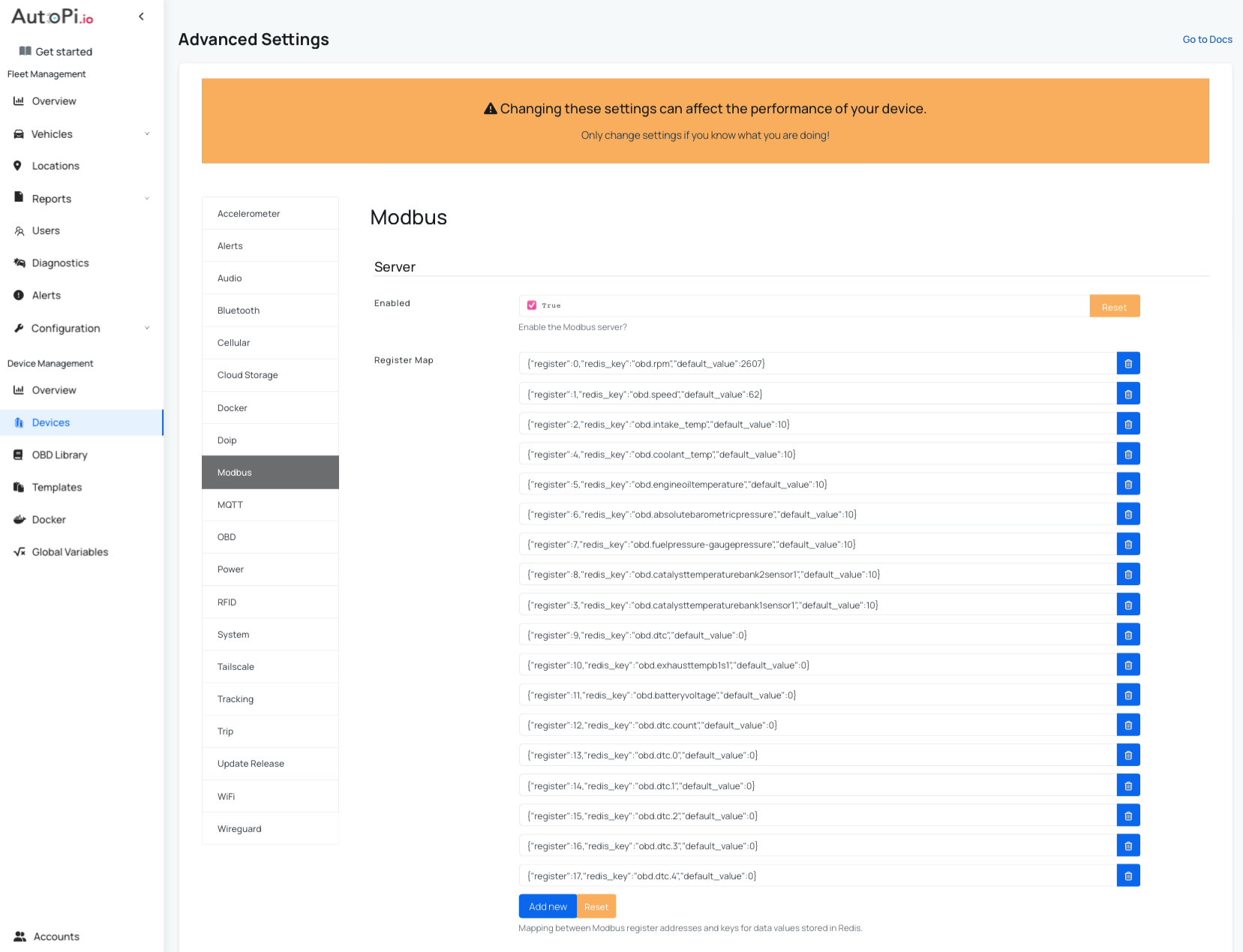
In this example:
- Register 0 exposes engine RPM
- Register 1 exposes vehicle speed
- Register 2 exposes intake temperature
- Register 4 exposes coolant temperature ...
Each Modbus client request for a specific register will return the corresponding vehicle data value from Redis cache.
Step 3 — Verify Loggers Are Running
Register values depend on active loggers. The redis_key in your register map must match the output field name of the corresponding logger.
Common OBD redis_key values:
| redis_key | Description |
|---|---|
obd.rpm | Engine RPM |
obd.speed | Vehicle speed |
obd.coolant_temp | Coolant temperature |
obd.fuel_level | Fuel level |
obd.throttle_pos | Throttle position |
Logger update intervals determine how frequently register values are refreshed. To adjust the interval, navigate to Loggers → Logger Name and update the configuration for the relevant PID logger.
Exposing Diagnostic Trouble Codes (DTCs)
To expose DTCs over Modbus, you must reserve a block of registers: one for the DTC count, followed by one register per DTC value.
Setup DTCs:
-
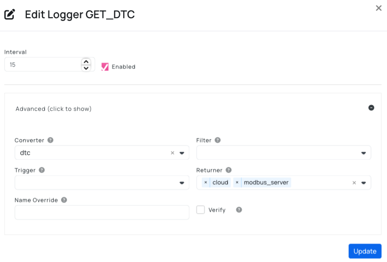
Create a DTC Logger
- Navigate to Device → Loggers → Create
- Create a new logger with these settings as shown on the picture below:
- Name:
GET_DTC - Converter:
dtc - Returner:
modbus_server
- Name:
- Click Save
-
Configure DTC Register Map
- Navigate to Device → Advanced Settings → Modbus → Register Map
- Add the following mappings to expose DTC data:
- DTC Count — Insert this to track the total number of active codes:
{"register":12,"redis_key":"obd.dtc.count","default_value":0} - DTC Code — Insert this to expose the first DTC code:
{"register":13,"redis_key":"obd.dtc.0","default_value":0}
- DTC Count — Insert this to track the total number of active codes:
- To add additional DTC slots, increment both the register address and DTC index (e.g.,
{"register":14,"redis_key":"obd.dtc.1","default_value":0}) - Click Save
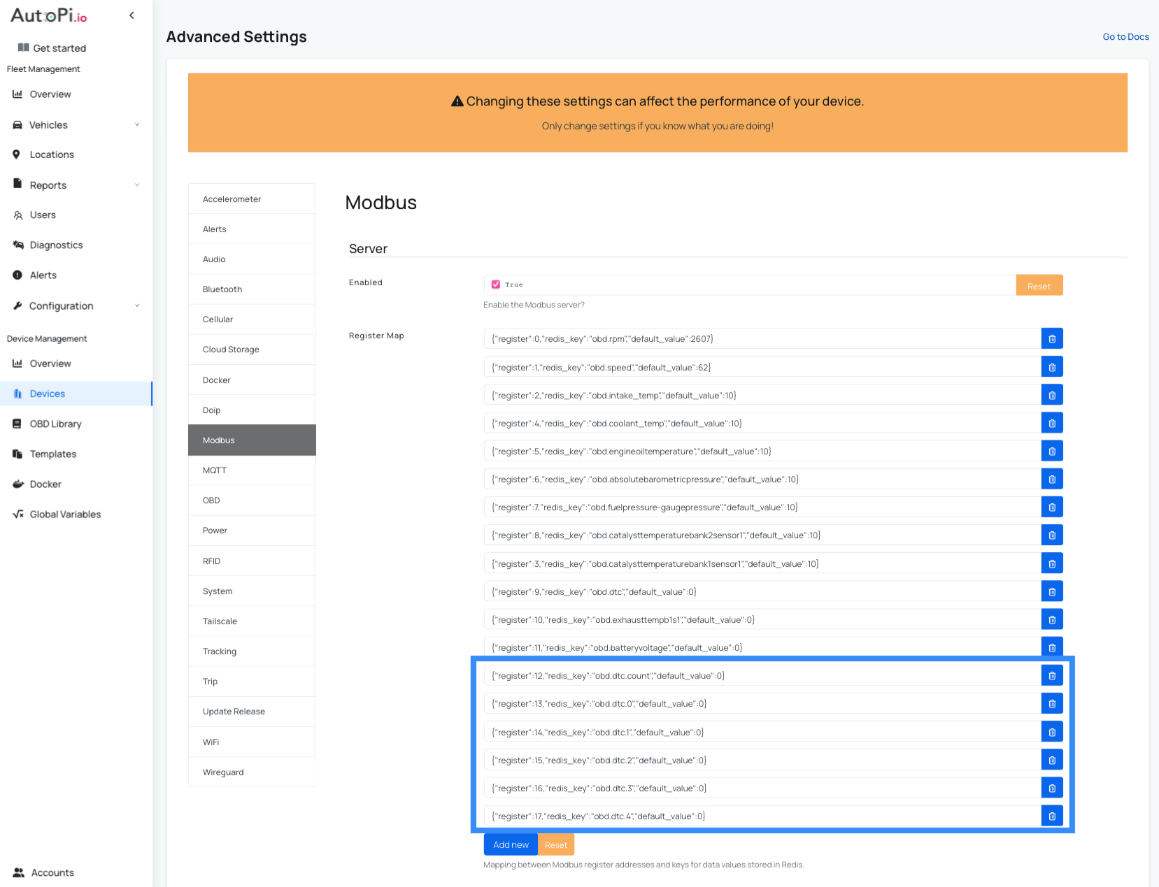
Note: In this example, the register allocation is as follows:
- Registers 0–11 — Reserved for vehicle signal loggers (RPM, speed, temperature, etc.)
- Registers 12–17 — Reserved for DTC data (register 12 for DTC count, registers 13–17 for up to 5 individual DTC codes).
Adjust these register numbers based on your actual setup. If you have more or fewer signal loggers, shift the DTC registers accordingly.
DTC Encoding
DTC codes are encoded as integers because Modbus does not support alphabetic characters. Use this encoding scheme:
| Category | Prefix | Example DTC | Encoded Value |
|---|---|---|---|
| Powertrain | P | P0301 | 10301 |
| Body | B | B1234 | 21234 |
| Chassis | C | C1234 | 31234 |
| Network | U | U9999 | 49999 |
- A value of
0indicates an empty slot.
Connecting a Modbus Client
Connect your Modbus client to the device's IP address on port 5020 (or whichever port you configured in Advanced Settings).
The following Modbus function codes are supported:
- Function Code 3 — Read Holding Registers
- Function Code 4 — Read Input Registers
Both function codes return the same register values.
Python Example
from pymodbus.client.sync import ModbusTcpClient

# Connect to the AutoPi device
client = ModbusTcpClient("192.168.4.1", port=5020)
client.connect()

# Read registers 0 and 1 (RPM and speed)
result = client.read_holding_registers(0, 2, unit=1)
print(result.registers)  # Output: [rpm_value, speed_value]

client.close()
 Buy AutoPi device
 Compare all AutoPi devices
 Contact our sales team