Create Loggers
Logging data is one of the core features of the AutoPi TMU CM4, allowing you to automatically record key data from your device for analysis, monitoring, or integration with other systems. After completing the Getting Started Guide, this is the next step to help you get the most out of your AutoPi TMU CM4 device.
This guide walks you through:
- Setting up CAN communication.
- Using the OBD Library.
- Creating and managing loggers.
- Linking logged data to dashboards.
Step 1: Setting up CAN Bus Protocol
Before creating loggers, ensure your CAN Bus is configured correctly. There are three available methods to set up a CAN Bus protocol: Auto-detection, manual setup or using CAN Analyzer. All of the methods are described below.
Tip: You can verify the protocol using the Cloud terminal command:
obd.protocol. You can also read more in this guide: OBD commands.
Auto-detection of the CAN Bus Protocol
Automatically detects the correct protocol. If successful, it will appear in:
- Events tab - you can see it as
system/obd/bus_connected.
- Device → Edit Device → Vehicle Editor → CAN Buses.
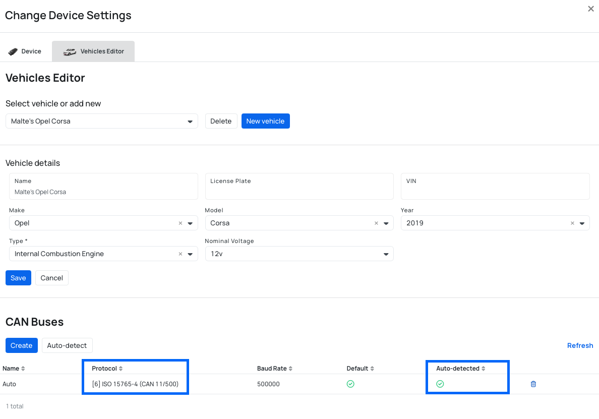
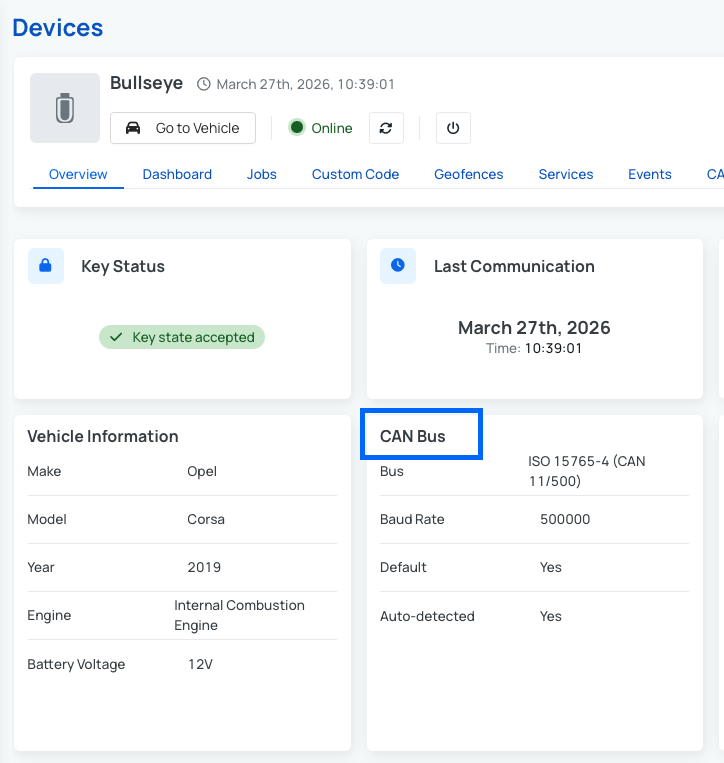
- Device -> Overview -> CAN Bus widget.
Manual setup of the CAN Bus Protocol
Steps to manually setup the CAN Bus:
- Navigate to device -> Edit Device → Vehicle Editor → CAN Buses -> Create.
- Fill out these information:
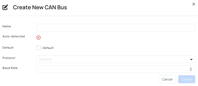
- Name - short name for your CAN Bus.
- Default - specify if you want to use this CAN Bus as default option.
- Protocol - select the protocol.
- Baud Rate - set up a baud rate.
- Click Create.
Use CAN Analyzer (Sniffer)
Use the sniffer to detect available CAN traffic and identify the correct protocol. You can read more at this guide: Using the Cloud CAN Analyzer.
Step 2: Browse the OBD Library
The OBD Library is where you define what data your device can read and you can then share this data across devices.
Community Library
Community Library contains shared PIDs from other users and free to be used. These PIDs are automatically filtered by your vehicle model (make/model/year).
In the Community Library, you can:
- Preview the PID by clicking it, and test the command on your vehicle.
- Add PIDs to My Library by selecting your device from the dropdown options for "Device" and by clicking on "Add to my library".
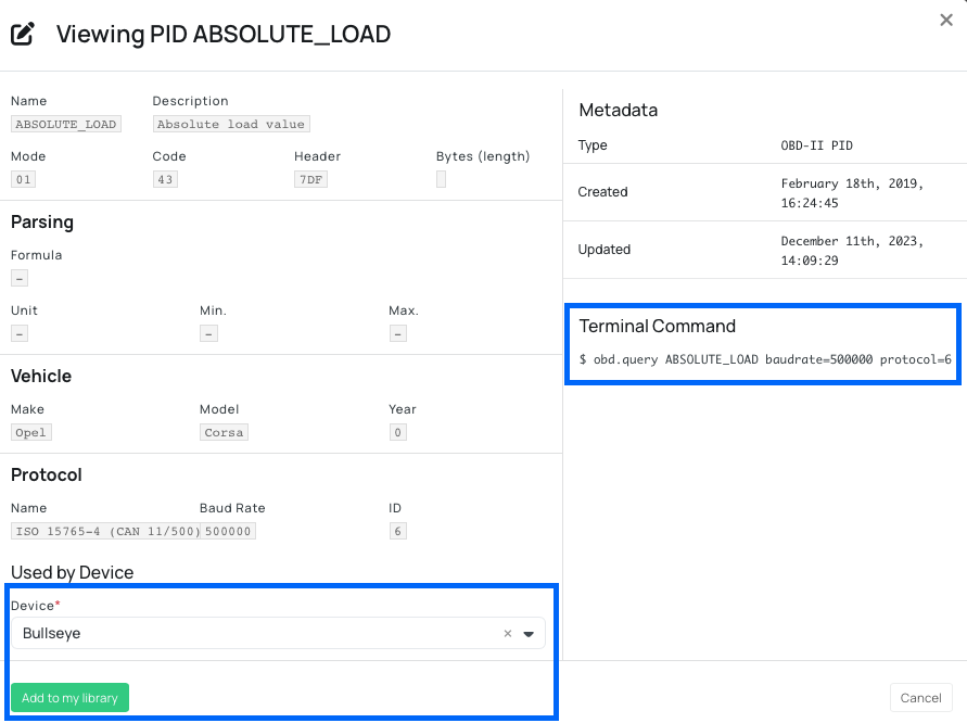
Note: Some PIDs may require adjustments depending on your vehicle.
If you want to learn more about how to find and use PIDs and add them to your Library, check out this guide: Community Library.
My Library
My Library is your personal collection of PIDs, CAN messages and CAN signals. There are different ways to add items to your Library. Such as:
Option 1: Import from Community Library
To add PIDs to My Library, go to Community Library and click on any PID you like, and by selecting your device and clicking on "Add to my library".
Option 2: Import DBC file (CAN messages/signals)
The Library supports importing both CAN messages and signals through DBC files. As an example, let's use this simple DBC file:
  VERSION "1.0"

  BO_ 938 FRONT_LEFT: 4 IO
    SG_ LEFT_SEAT_TEMP: 0|8@1+ (1,0) [0|0] "c" ECU1
    SG_ LEFT_BACK_TEMP: 8|16@1+ (1,0) [0|0] "c" ECU1

  BO_ 937 FRONT_RIGHT: 4 IO
    SG_ RIGHT_SEAT_TEMP: 0|8@1+ (1,0) [0|0] "c" ECU1
    SG_ RIGHT_BACK_TEMP: 8|16@1+ (1,0) [0|0] "c" ECU1

  CM_ SG_ 938 LEFT_SEAT_TEMP "Temperature of the front left seat";
Option 3: Import JSON file (PIDs)
The Library also supports importing PIDs using JSON format. Unlike CAN messages and signals, there's no industry standard file format for PIDs. Therefore, there's a custom JSON based format that you need to follow.
This is an example PID JSON file:
[
	{
		"fields": {
			"type": "PTY",
			"header": "700",
			"mode": "220",
			"code": "0103",
			"bytes": null,
			"frames": null,
			"strict": false,
			"formula": "bytes_to_int(messages[0].data[-3:])",
			"unit": "km",
			"min": null,
			"max": null,
			"datatype": null,
			"parent": null,
			"name": "TractorLighting",
			"description": "Tractor's light emission",
			"hash": "",
			"initial_hash": null,
			"can_extended_address": null,
			"can_flow_control": {
				"filter": {
					"pattern": "708",
					"mask": "7FF"
				},
				"id_pair": {
					"receiver_id": "700",
					"transmitter_id": "708"
				}
			},
			"can_messages": []
		}
	},
	{
		"fields": {
			"type": "PTY",
            ...
        }
	}
]
Option 4: Create manually
Option 4.1: Create a PID Manually
Items that are created with the OBD-II PID type are PIDs that are a part of the OBD-II standard which is used by most internal combustion engine (ICE) vehicles.
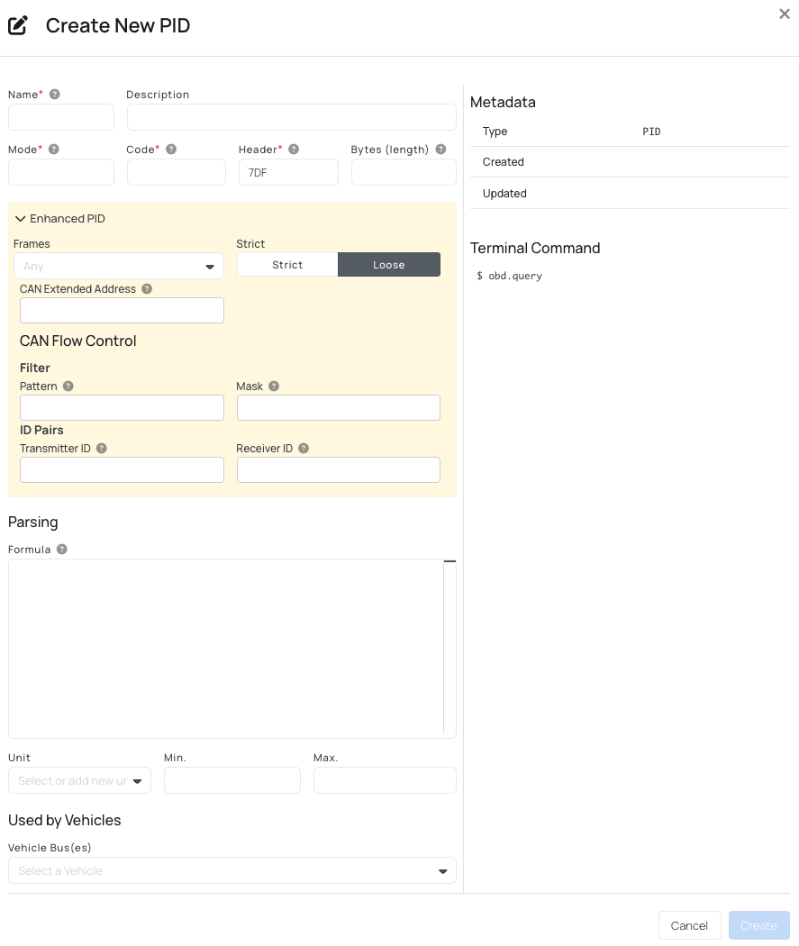
To create a new PID, you need to fill out these:
- Name: short name of the PID that's being created.
- Description: optional description of the PID. This can be very useful if plan to share the PID with the rest of the community.
- Mode: this is the mode that the PID is working in. We will type 01 in our example. However there are different modes you can use:
01- show current data .02- show freeze frame data.03- show stored Diagnostic Trouble Codes.04- Clear Diagnostic Trouble Codes and stored values.05- test results, oxygen sensor monitoring (non CAN only).06- test results, other component/system monitoring (test results, oxzgen sensor monitoring for CAN only).07- show pending Diagnostic Trouble Codes (detected during current or last driving cycle).08- control operation of on-board component/system.09- request vehicle information.0A- permanent Diagnostic Trouble Codes (DTCs)(Cleared DTCs).
- Code: the hexadecimal representation of the requested PID. In this case, the code is 0C and so we will specify that.
- Header: the header used to request the PID. 7DF is the standard header value for external OBD-II test equipment, so this is the one we'll use.
- Bytes: This is the expected length of the response.
- Enhanced PID:
- Frames: how many can frames are expected for this PID response. If chosen
any- accept single-frame or multi-frame responses. - Strict: choose between strict and loose. If strict is set, it will ensure that the device is exactly the length of bytes specified in the bytes field.
- CAN Extended Address - with CAN Extended Addressing, an extra byte inside the data payload is used to specify the target.
- Filter Pattern - the expected CAN ID or part of it you want to match.
- Filter Mask - defines which bits matter in the pattern. Bits set to "1" - must match; bits set to "0" - ignore.
- ID Pairs Transmitter ID - the CAN ID your tool sends from, usually something like
0x7DF. - ID Pairs Receiver ID - the CAN ID you expect the response from, example
0x7DF.
- Frames: how many can frames are expected for this PID response. If chosen
- Formula: A Formula is a dynamic expression evaluated at runtime that converts raw vehicle response data into meaningful values. It operates within a constrained execution environment with predefined helper functions and message objects.
- Example of custom formula:
bytes_to_int(message.data[4:8])
- Example of custom formula:
- Unit: The unit of the data (more examples: km/h, percentage, liters, etc.)
- Min: The minimum value that this PID can return.
- Max: The maximum value that this PID can return.
- Vehicle Bus(es): A list of CAN busses that support this PID. If a vehicle is able to recognize this PID and return data back, it is recommended that you add the bus of that vehicle to the list.
This is how Custom Formula is evaluated:
  def calc_formula(expression, message_data, default=None):

      if not message_data:
          log.warn("No data found to calculate formula: {:}".format(expression))

          return default

      if type(message_data) == bytearray:
          message_data = [TranslatableMessage(message_data)]

      try:
          return eval(expression, {}, {
              # Helper functions
              "bytes_to_int": bytes_to_int,
              "bytes_to_hex": bytes_to_hex,
              "twos_comp": twos_comp,
              # Message data
              "message": message_data[0],
              "messages": message_data
          })
      except Exception as ex:
          log.exception("Failed to calculate formula")

          raise Exception("Failed to calculate formula: {:}".format(ex))
Therefore using the formulas defined in the calculate_formula - and what comes in is an array of bytes, so each index contains one byte!
Formulas are evaluated using a restricted eval environment. The expression has access to:
- Helper Functions
bytes_to_int— converts raw byte sequences into an integer.bytes_to_hex— converts raw byte sequences into a hexadecimal string.twos_comp— interprets a value using two’s complement (for signed values).
- Message Context
message— the first response message (most common use case).messages— a list of all response messages (useful for multi-frame responses).
Option 4.2: Create a PGN Manually
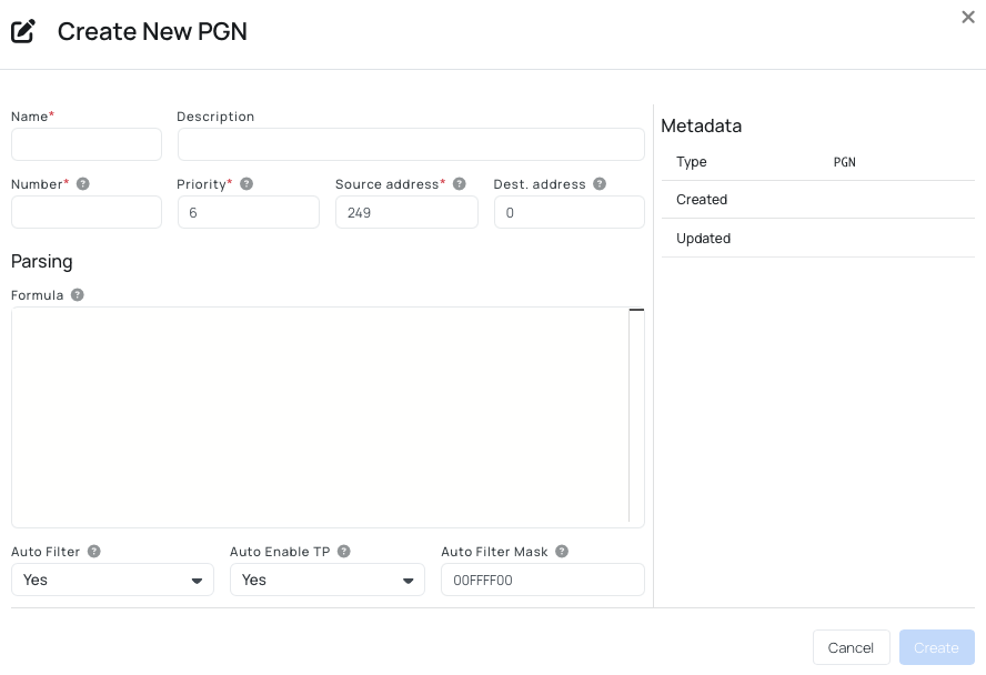
To create a new PGN, you need to fill out these:
- Name: short name of the CAN message that is being created.
- Description: an optional description for this PGN.
- Number: number of the PGN to query.
- Priority: the priority to use for the request frame.
- Source address: the source address of the request frame.
- Destination address: the destination address of the request frame.
- Formula: Python code that decodes the raw byte data to a value.
- Auto Filter: ensure to apply filtering to only include reply frame(s) for the specific PGN.
- Auto Enable TP: automatically enable Transport Protocol (TP) for multi-frame messages.
- Auto Filter Mask: the bitmask to use when the filter is applied (to all frame types including TP).
Option 4.3: Create a CAN Message Manually
CAN messages are continuously broadcasted on the CAN bus and do not require any requests to be made. However, to be able to make any sense of the CAN messages, we need to specify which bytes within a message corresponds to which data point from the vehicle.

To create a new CAN Message, you need to fill out these:
- Name: short name of the CAN message that's being created.
- Description: an optional description for this CAN message.
- Header: the hexadecimal representation of the header that this CAN message is recognized by.
- Bytes: How long is the CAN message?
- Sender: The name of the transmitting node of this CAN message - usually defined inside a DBC file, but can be any short string.
- X CAN Signals: This is a list of CAN signals that can be found inside a CAN message. "X" represents the number of created signals. Each CAN signal has the same form fields:
- Name: short name of the CAN signal.
- Description: an optional description of this CAN signal.
- Endian: the endianness of this CAN signal - which is the most significant byte.
- Sign: defines if the CAN signal should be treated as a signed or unsigned number.
- Start: defines the starting bit of the CAN signal.
- Length: how long the CAN signal is.
- Factor: used to calculate the real value off of the CAN signal. Formula:
VALUE = (RAW_VALUE * FACTOR) + OFFSET - Offset: used to calculate the real value off of the CAN signal.
- Unit: the unit of the value returned.
- Min: the minimum value possible for this CAN signal.
- Max: the maximum value possible for this CAN signal.
- Receivers: the name of the receiving node of this CAN message - usually defined inside a DBC file, but can be any short string.
- Vehicle bus(es): A list of CAN busses that support this CAN message. If a vehicle continuously writes this CAN message on its CAN bus, it is recommended that you add the bus of that vehicle to the list.
Step 3: Setting up Loggers
After identifying which signals should be logged in Step 2 (browsing the OBD Library and adding entries to your library), the next step is to configure the device to actively log this data.
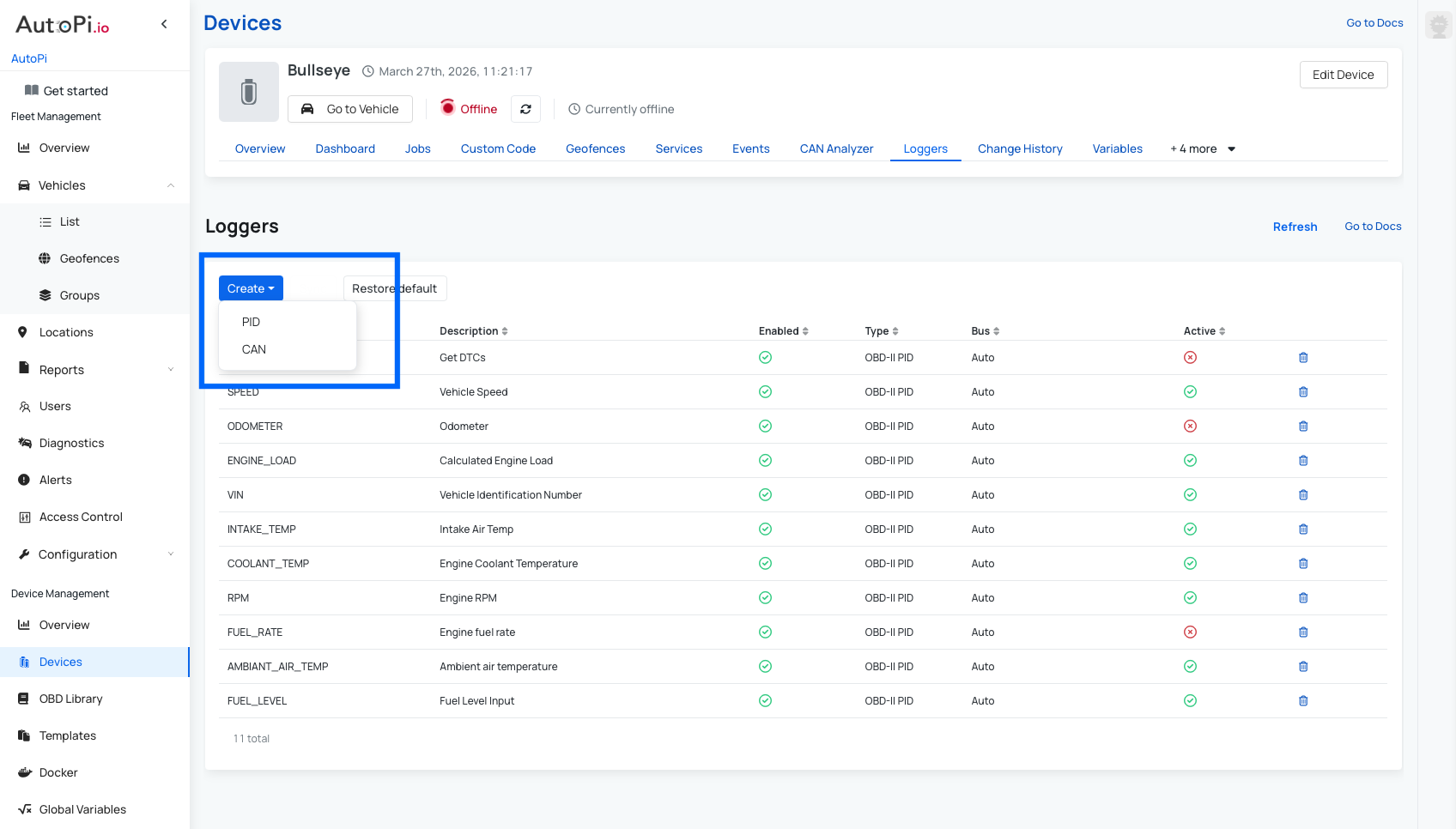
Steps to Create a new Logger:
- Navigate to: Device → Loggers.
- Click the Create button.
- Select one of the available logger types:
- PID Logger - used for logging PIDs via standard OBD-II communication.
- CAN Logger - used for logging raw or decoded CAN bus messages directly from the vehicle network.
- Fill out the mandatory fields.
- Save.
Create PID Logger (Simpler)
Types:
- OBD-II PID
- Proprietary PID.
In order to create a PID Logger, you need to fill out these information:
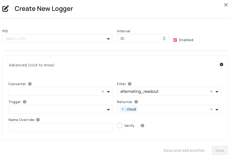
-
Basic information:
- Select a PID - choose a PID you want to log.
- Interval - setup a interval on how often the logger log the data in seconds.
- Enabled - decide if you want this logger to be enabled or not.
-
Advanced:
- Converter - alters the result of the Logger to give another output.
- Filter - filter the output that is send to returner. There are two options:
alternating_readout- filter that only returns alternating/changed results.alternating_dtc- filters out repeating Diagnostics Trouble Codes (DTCs).
- Trigger - choose a trigger that can send an event.
- Returner - choose a returner that sends data. We have a different default returners:
cloud_https/cloud- sending data to a http endpoint.Note: this setting defaults to AutoPi backend but can be changed in the advanced settings under Cloud storage.
cloud_jsonl- publishing data to a Kafka broker.mqtt- publishing data to your own mqtt server and is highly configurable. This can be configured in the Advanced settings > Cloud Storage.
- Name override - override name of the PID. This functionality is useful for when you want to test different loggers with the same name.
- Verify - if enabled, it verifies the protocol on each request.
You can also read more about how to create PID loggers in depth in this guide: Create PID Looggers.
If you want to investigate the raw request and response messages of PID queries, you can read this guide: Debug Raw PID Queries.
Default OBD-II PID Loggers
In the AutoPi Cloud, under the Loggers section, you will find a set of standard loggers preconfigured. These are particularly useful when working with a basic OBD-II vehicle and can help you get started with data logging quickly. If you have made changes to the loggers, you can always use the “Restore to Default” option to revert to the standard configuration. The default OBD-II PID loggers available in the AutoPi Cloud include:
- Fuel level
- Coolant temperature
- RPM
- Speed
- Get DTCs (Diagnostic trouble codes)
- Ambient air temperature
- Engine load
- Intake temperature These standard loggers provide a solid baseline for monitoring common vehicle parameters.
Create CAN Logger (Advanced)
Prerequisite: Signals must exist in My Library.
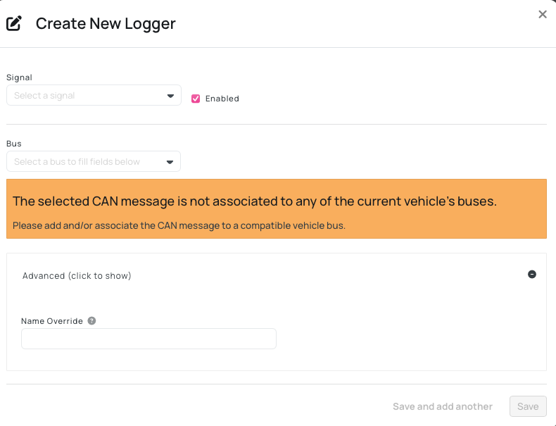
In order to create a CAN Logger, you need to fill out these information:
- Signal - pick the signal you want to use.
- Enabled - decide if you want this logger to be enabled or not.
- Bus - specify the CAN Bus. This setting is prefilled based on the signal chosen.
- Advanced:
- Name override - override name of the CAN signal.
You can also read more about how to create CAN Logger in depth in this guide: Create CAN Signal Loggers.
There is also a possibility to listen for raw CAN data on the OBD port and log the RAW CAN messages, you can read more about that in this guide: Log Raw CAN Messages.
Bulk Configuration via Importing a DBC File/JSON File
If you prefer not to configure loggers individually, you can use the DBC/JSON import functionality available in the OBD Library - My Library. This approach is recommended when working with larger signal sets or standardized CAN databases, as it reduces manual setup and ensures consistency.
This method allows you to:
- Import a DBC or JSON file containing CAN message and signal definitions.
- Automatically parse and validate CAN frames and associated signals.
- Review all available signals before applying configuration.
How to Import a DBC file:
- Go to OBD Library/ My Library.
- Click on Import.
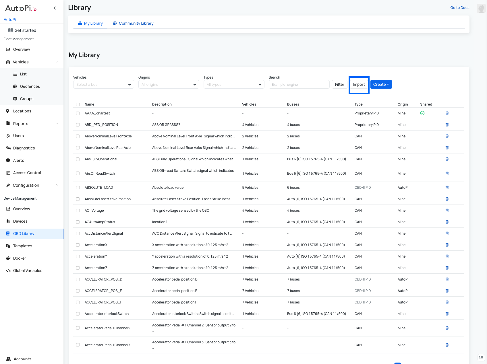
- Click on import file.
- Upload the file.
- Specify the content: CAN or PID.
- Name - choose the name if desired.
- Validate the file.
- Choose which CAN or PID you want to create and which ones you want to ignore.
- Once you go through the file, click upload. Now all your chosen CAN or PID are uploaded to "My Library".
- Now you can find them in the table and by clicking on it you can specify which vehicle you want this to be associated to.
- Save your changes.
Imported items will now be available for logger creation.
Step 4: Link your Loggers to Your Dashboard
For a widget to display data, it must be linked to the appropriate logger. If you add or edit loggers, you will also need to update the corresponding dashboard widgets.
Widgets can display data in several formats, including:
- Graphs
- Line charts
- State timelines
- Gauges ...
You can also configure widgets to show raw, average, minimum, or maximum values depending on your needs.
After adjusting your widget settings:
- Click Save.
- Refresh the widget using the circle icon in the top-right corner.
If the data appears after refreshing, your configuration is correct. If you have just created a new logger, the device may need another vehicle trip before the required data is collected.
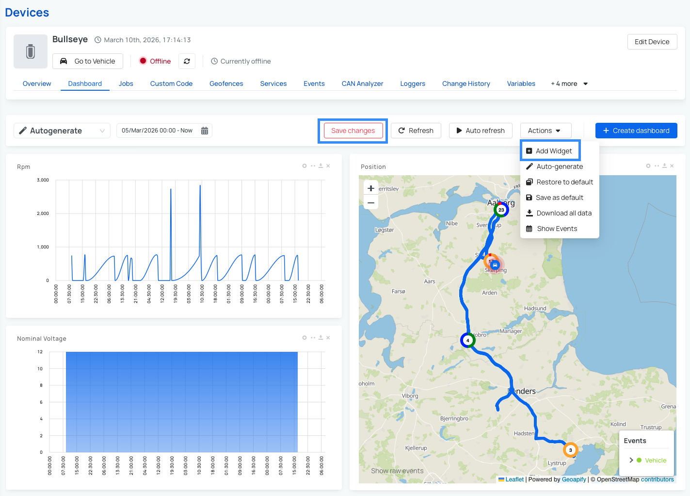
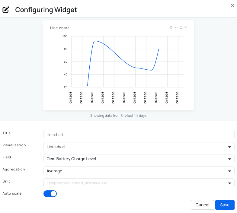
Create a Widget
To create a new widget:
- Navigate to Dashboard.
- Click the Actions button in the upper-right corner.
- Select Add widget.
- Fill out the required information.
- Click Save.
- Save your dashboard changes to apply the widget.
Note: For a more detailed explanation of widget configuration, see this guide: Configure the widget settings.
Note: When choosing the Field, the list only shows data that has already been received from the device. If the logger you are looking for is not in the list, the device may not be reading it. In this case, go to Loggers, enable the logger, or update its settings.
Note: A logger must be configured beforehand, otherwise the widget will not have any data to display.
Edit an Existing Widget
To edit an existing widget:
- Navigate to Dashboard.
- Click the two-dot icon on the widget you want to update.
- Make your desired changes.
- Click Save.
Note: Ensure the configuration, especially the Field section, matches the data being logged.
Auto-Generate Widgets
The Auto-generate feature allows you to quickly create widgets based on the data received from the device. This saves time compared to creating each widget manually. Auto-generated widgets are based on real data, and you can adjust them afterward if needed (for example changing aggregation or visualization).
How to use Auto-generate:
- Navigate to Dashboard.
- Click the Actions button in the upper-right corner.
- Select Auto-generate.
- Make any desired changes.
- Click Save.
Note: By default, there is usually an auto-generated dashboard created for your device, which you can find in the dashboard dropdown menu.
When you are satisfied with your dashboard configuration, remember to save your layout through Widget Actions to keep your settings for future sessions.
Summary
- Configure CAN Bus correctly first.
- Use OBD Library to define signals and PIDs.
- Create PID or CAN loggers depending on your needs.
- Link loggers to dashboards for visualization.
This setup allows you to build powerful data collection and monitoring workflows tailored to your vehicle.
 Buy AutoPi device
 Compare all AutoPi devices
 Contact our sales team