User guide
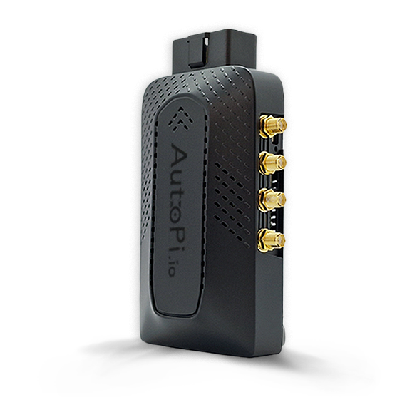
Our newest AutoPi CAN-FD Pro device has some new features that are not available on our other devices. This guide will walk you through everything you need to know about the CAN Logging feature on our AutoPi CAN-FD Pro device. Whether you're setting up your first logger or exploring advanced options, we've made it easy to follow and fully customizable to suit your needs.
CAN Logging on the AutoPi CAN-FD Pro is different from the Loggers feature available on our other device AutoPi TMU CM4.
What is CAN Logging? CAN Logging captures traffic from your vehicle’s CAN bus using two dedicated interfaces: can0 and can1. These logs can include raw or decoded data, depending on your configuration.
logger.status command
This command is a great tool to see the current status of your data logger(s) in real time. You can run this command in 3 ways:
- If the device is connected to the internet it can be done through the cloud terminal on AutoPi cloud.
- If you have direct SSH access to the device via LAN or VPN you can use the autopi terminal command.
- You can check out this guide: How to SSH to your device
- For using Tailscale, you can check out this guide: How to connect to Tailscale
- If you are nearby the device and can connect to it's local WiFi hotspot you can do it from the local admin UI on local.autopi.io. Here is a guide: Local development workflow
Below is an example of the output of the command:
channels:
  can0:
    interface:
      autodetect:
        in_progress: false
        last_results:
          any_passive:
            bitrate: 500000
            frames_per_second: 710
            has_11bit_identifiers: true
            has_29bit_identifiers: false
            performed_at: '2025-05-07T09:50:43.347462'
            success: true
      bitrate: 500000
    loggers:
      raw:
        current_fps: 584.95
        decoders:
          dbc:
            failed_messages_count: 140000
            output_file_pattern: /opt/autopi/can0/loggers/raw/decoders/dbc/output/{input:}.jsonl
            output_handlers:
            - destination_path: s3://my-datalogger/a1eeabbd-cffa-f7c4-31a5-49b2c2340d3d/can0/decoded
              uploaded_files_count: 2
            total_messages_count: 140000
            type: STANDARD
        output_file_pattern: /opt/autopi/can0/loggers/raw/output/{ts:%Y%m%d%H%M}.log
        output_handlers:
        - destination_path: s3://my-datalogger/a1eeabbd-cffa-f7c4-31a5-49b2c2340d3d/can0/raw
          uploaded_files_count: 2
        received_error_frames_count: 613
        received_frames_count: 111101
  can1:
    interface:
      autodetect:
        in_progress: false
        last_results:
          any_passive:
            bitrate: 500000
            frames_per_second: 544
            has_11bit_identifiers: true
            has_29bit_identifiers: false
            performed_at: '2025-05-07T09:50:44.198244'
            success: true
      bitrate: 500000
    loggers:
      raw:
        current_fps: 586.66
        decoders:
          dbc:
            output_file_pattern: /opt/autopi/can1/loggers/raw/decoders/dbc/output/{input:}.mf4
            total_messages_count: 0
            type: ASAMMDF
        output_file_pattern: /opt/autopi/can1/loggers/raw/output/{ts:%Y%m%d%H%M}.log
        received_error_frames_count: 613
        received_frames_count: 113725
disks:
  /:
    free_space: 3 GB
    housekeeper:
      deleted_files_count: 0
      total_space_freed: 0 bytes
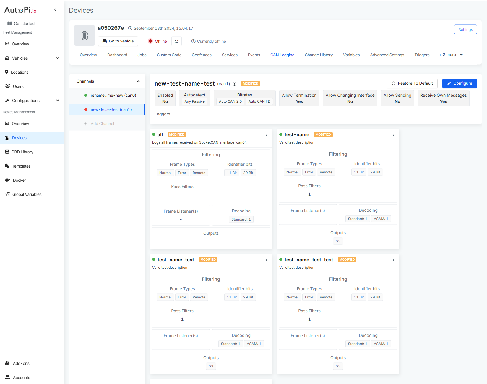
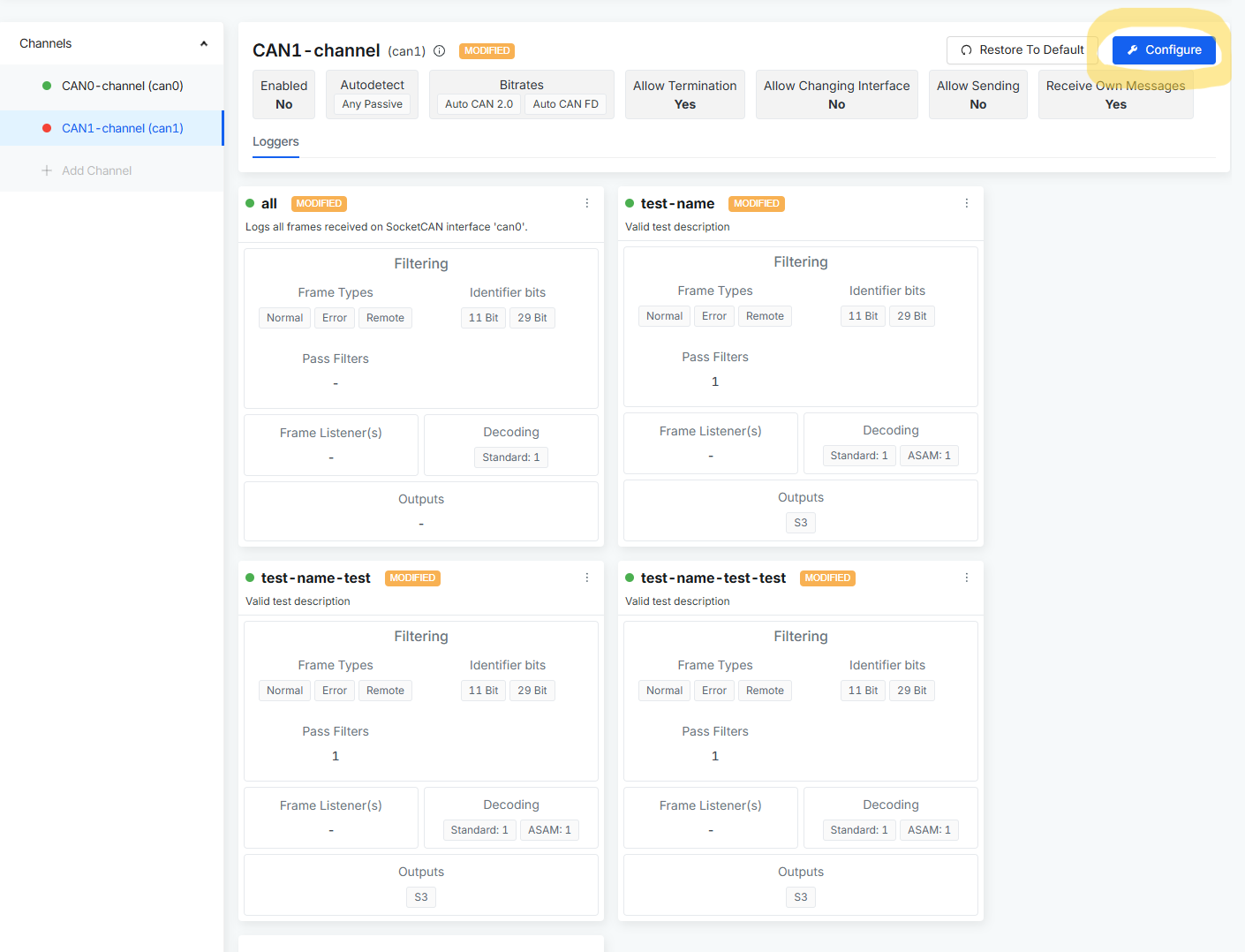
Channels
A channel is a pathway through which the device listens to or communicates on the CAN bus. Most vehicles have one or two CAN buses. The AutoPi CAN-FD Pro supports two channels out of the box: can0 and can1. CAN communication is based on an agreed bitrate (speed of the amount of data processed within one second). Think of it like tuning two radios to the same frequency—you need to match speeds to understand each other. If you don’t know the bitrate, AutoPi CAN-FD Pro device has functionality to Autodetect to help you find the correct bitrate - by selecting one or more methods to detect the CAN bus and the active protocol(s). A passive method will only listen for broadcast traffic. An active method will attempt to send a request and then wait for a valid response.
How to Configure CAN Channels?
By default, can0 and can1 channels are preconfigured with standard values. But you can fully customize them.
Opening the configuration of the CAN channel
- Go to the Devices section.
- Click on the device you want to configure.
- Select the CAN Logging tab.
- Click on the channel you want to edit.
- Click the "Configure" button in the top-right corner.
Detailed description of steps to configuring/creating CAN channel
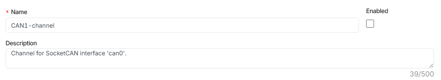
Step 1: Name & Description of the CAN channel
- Name the channel or update the existing name.
- Add a description to clarify its purpose.
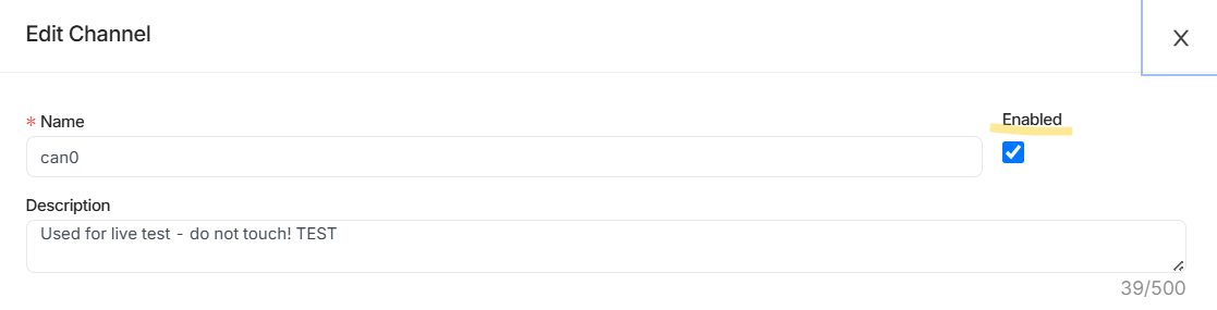
Step 2: Enable or Disable CAN channel
- Use the checkbox to either enable or disable this channel. When disabled, CAN channel is not running and therefore not listening to CAN Bus.
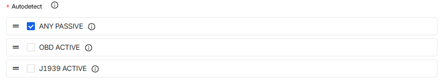
Step 3: Autodetect (How to find the correct bitrate)
-
This is a way to detect the CAN Bus. Type of the CAN bus can different from vehicle to vehicle (with different bitrates (speed)). Therefore, we need to detect the correct type of CAN Bus but also find the correct bitrate before we can start recording data from the device.
-
Choose from three detection strategies to ensure there is data:
- Any (passive) – Passively listens for CAN messages on the bus without actively sending any messages. This is set as default, as it is the safest strategy because you are just trying to find out if there is any activity on the bitrate.
- OBD (active) – Sends an OBD-II PID request message and waits for a response to detect if the protocol is supported. If the response is received that means that the protocol is supported.
- J1939 (active) – Sends a J1939 PGN request message and waits for a response to detect if the protocol is supported. If the response is received that means that the protocol is supported.
 warning
In some cases, the vehicle may produce MIL (malfunction indicator lamp) notifications on the dashboard when active strategies are used for protocols that are not supported by the vehicle.
Every time the Autodetection is used, it triggers an events that could be seen in the events section. This should help users to understand a little better what is happening on a device. These are some of the examples for the events:
vehicle/bus/can0/autodetectedvehicle/bus/can0/autodetect/any_passive/successfulvehicle/bus/can0/autodetect/any_passive/unsuccessful
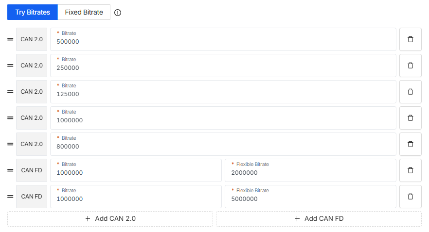
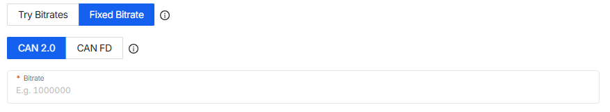
Step 4: Try Bitrates or Use Fixed Bitrate
- As mentioned above, you need to find the correct bitrate for your vehicle. The deafult list for Try Bitrates includes some of the most common used bitrates to make this process easier for you. This step allows you to make sure that you can receive any data by listening to these settings.
- You have 2 options here:
- 1. Try Bitrates (Auto Mode):
If you're unsure about your vehicle’s bitrate, this is the best choice.
The device will automatically scan through a list of common CAN 2.0 and CAN FD bitrates.
It opens one channel, listens for about a second, then tries the next—until it locks onto the right one, basically the device tries different bitrates until it finds the one that matches your vehicle.
You can reorder the bitrate list and add your own based on your specific setup. Just use the 2 line icon on the left side.
- 2. Fixed Bitrate (Manual Mode):
Already know the exact bitrates for your CAN 2.0 and/or CAN FD? Just input them directly. This saves time and ensures consistent communication.
Step 5: Advanced Channel Settings
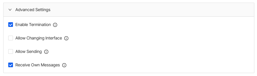
Under Advanced Settings you’ll find a few more options for extra settings:
- Enable Termination – Enables physical CAN bus termination of ~120 ohms for this channel.
- Allow Changing Interface – Permit to make changes to the underlying CAN interface? This includes changing the bitrate and bringing the interface up and down etc. If disabled, the CAN interface will be used as is without any prior setup.
- Allow Sending – Permit sending of CAN frames for this channel. If disabled, an error will be returned when attempting to send a CAN message.
- Receive Own Messages – Allows the device to also listen to messages it sends (useful for testing/debugging).
Loggers
Every channels can have one or multiple loggers set up. A CAN logger records all the CAN bus traffic detected through the can0 and can1 interfaces. This data can be raw or decoded, depending on how you configure the logger.
How to create CAN Logger?
Setting up a CAN logger is easy and flexible. We’ve provided default values for most fields, but you can customize everything to match your specific requirements.
Step 1: General information
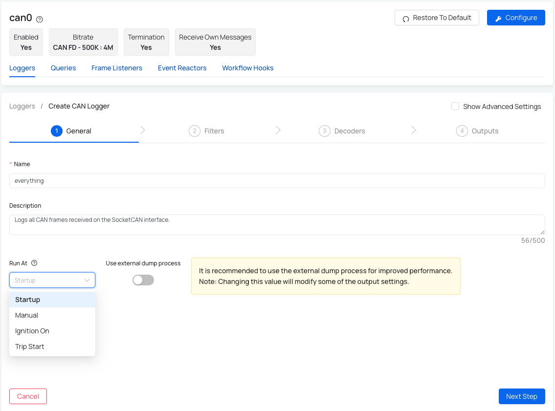
- Start by entering:
- Name – the name you want to give to this logger.
- Description (optional) – helpful if you want to add details about the logger's purpose.
- Run At - defines when this logger runs (e.g., at startup, on ignition on, on trip start or manually started).
- Use external dump process - it is recommended to use the external dump process for improved performance.
- Worker Settings (advanced) -
- Interval - you can specify the time period between reading out received CAN frames from the internal buffer.
- Start Delay - amount of seconds before the worker starts execution.
Step 2: Filters
Use filters to control which types of CAN frames are logged. This settings allow you to filter the type of data you want to be logged for your specific use case.
If you set up decoder for your CAN logger, the filters are automatically applied even tho they are not visible in this step. For this to work, it requires that it is enabled on the logger: Automatically add pass filters for all DBC message identifiers.
Scenario 1 - you have enabled the "Use external dump process" in the previous step and therefore your second step: Filters looks like this:
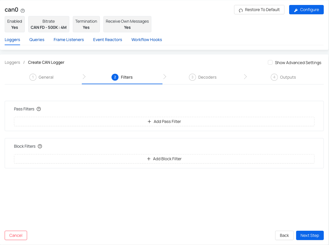
Therefore in this step you can add any Pass and Block Filters:
-
Add Pass Filter - only CAN frames with identifiers that match a pass filter will be included. To add a new pass filter, you'll need to specify the identifier bit length, ID, and a mask.
-
Add Block Filter - only CAN frames with identifiers that match a block filter will be excluded. To add a new block filter, you'll need to specify the identifier bit length, ID, and a mask.
Scenario 2 - you have disabled the "Use external dump process" in the previous step and therefore your second step: Filters looks like this:
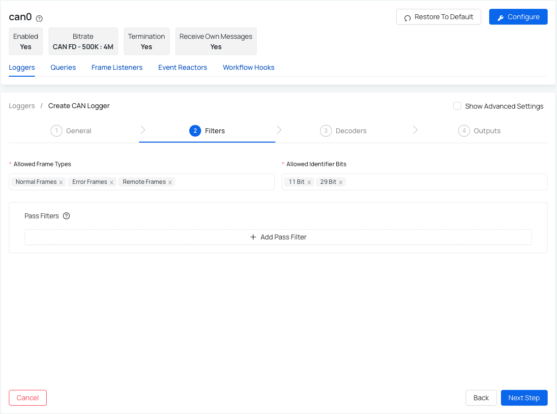
Therefore in this step you can specify Allowed frame types and allowed identifier bits as well as add any Pass Filters:
- Allowed Frame Types - choose from normal, error, and remote frames (all of the CAN messages has at least one of these frames).
- Allowed Identifier Bits - supports both 11-bit (standard) and 29-bit (extended) identifiers.
- Add Pass Filters (optional) - only CAN frames that match these filters will be logged.
- To add a new filter, you'll need to specify the identifier bit length, ID, and a mask.
If you don't know anything about a bit masking, it is better to use the default value inside the Pass Filters (there are different default values for 11 bit and 29 bits).
Step 3: Decoders
This step allows you to decode (translate) raw CAN data using Standard decoder or ASAM decoder. This step doesn't come up with pre-set default values, as this is fully customizable for user. Once you import a DBC file, you can set up some additional settings in order for your device to be able to decode the data based on your requirements.
How to setup decoding for your device?
Follow these steps to configure CAN data decoding:
- Go to your Device and navigate to CAN Logging tab.
- Create a new logger or edit an existing one.
- Navigate to Step 3: Decoders.
- Select the decoder type you want to use (Standard or ASAM).
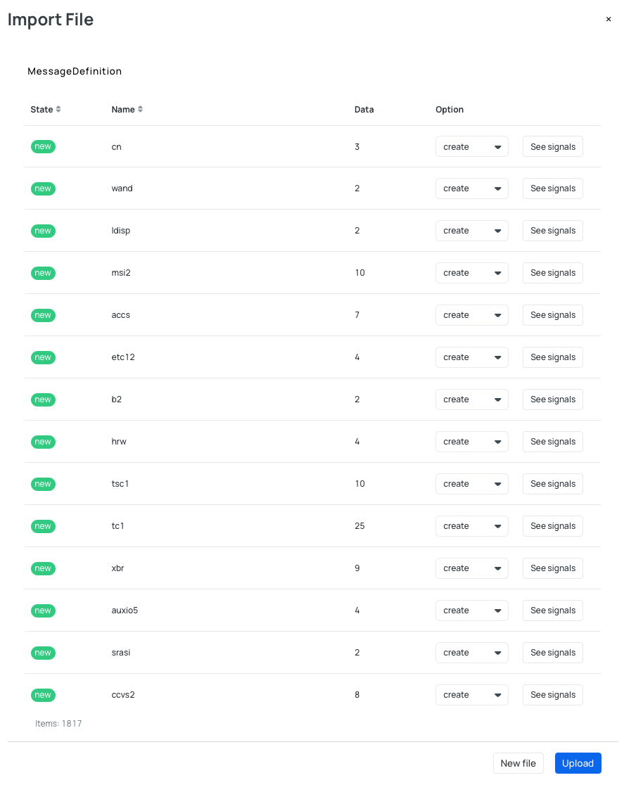
- Import your DBC file.
- After importing the DBC file, select only the signals you want to decode from the list. This allows you to pick specific signals without needing to modify or split the DBC file.
- Once the data is decoded, it can be accessed either locally on the device, or via an Amazon S3 bucket, depending on how you have configured the Outputs.
AutoPi CAN-FD Pro supports 2 types of decoders:
- Standard decoder - Using the standard decoder is faster than ASAM. Supported formats are CSV, JSONL and LOG.
- ASAM Decoder - The ASAM decoder is slower than the standard. Supported format is MDF4 - a binary file format for recording e.g. CAN and CAN FD data.
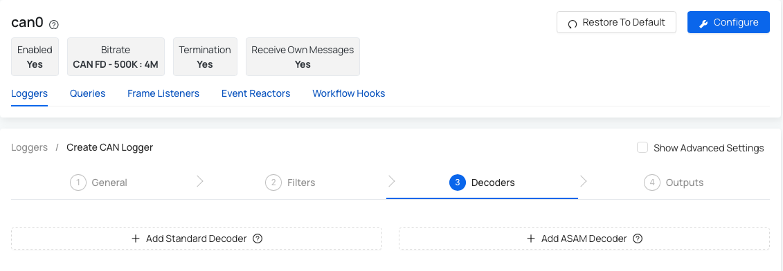
Option 1: Add Standard decoder
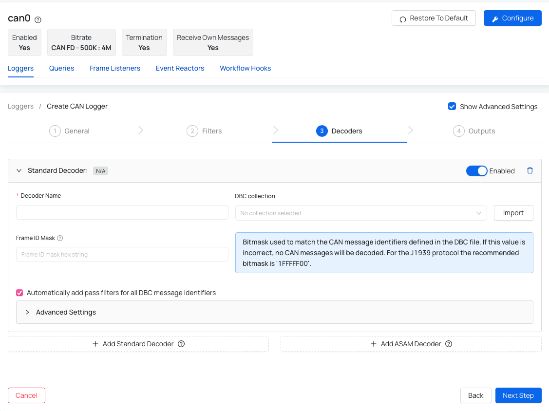
- Decoder Name - name your decoder.
- DBC Collection - select the desired DBC file from the dropdown or use "Import" button to import a new file.
- Frame ID Mask (optional) - help you determine how much needs to match before you have a match.
- Automatically add pass filters for all DBC message identifiers (optional) - this setting adds pass filters to the logger for all the selected CAN messages in the DBC file. This way, only those messages that can be decoded are logged.
- Library File Path Pattern (advanced) - the path to the message definition library file used for decoding the raw CAN messages.
- Strict mode (advanced) - prohibits overlapping fields / multiplexing when rendering DBC file.
After you choose or import the DBC file you are able to set up the CAN messages and signals based on your preference. After you validate the file, you will be presented with the list of CAN messages and signals. You can decide if you want to create or ignore the specific message or signal. If you create one that was already created, it will be updated. There is also one important technical value that needs to be set correctly: Frame ID Mask. Frame ID Mask will help you determine how much needs to match before you have a match.
Frame ID Mask: is a bitmask used to match the CAN message identifiers defined in the DBC file. If this value is incorrect, no CAN messages will be decoded. For the J1939 protocol the recommended bitmask is ´1FFFFF00´.
Option 2: Add ASAM decoder
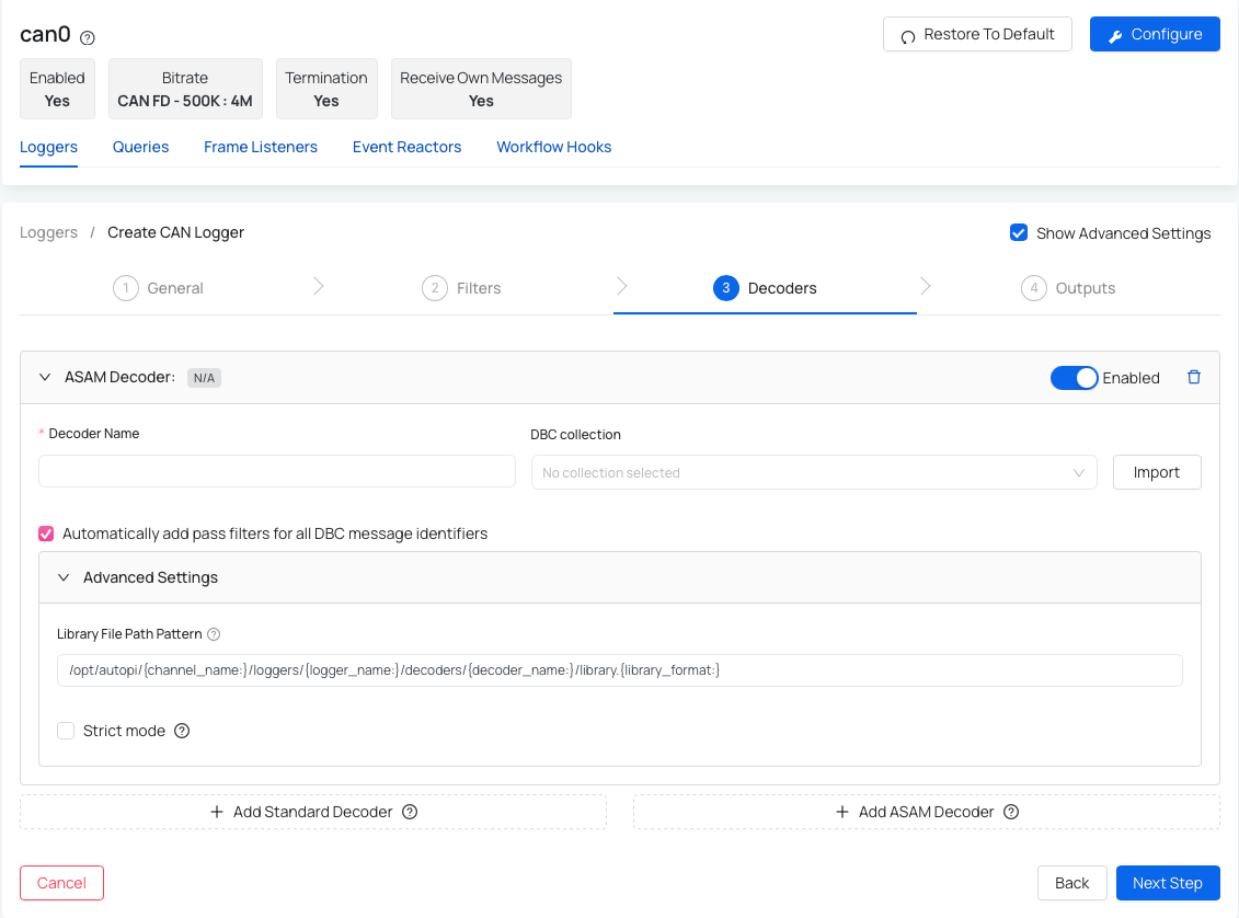
- Decoder name - name your decoder.
- DBC Collection - select the desired DBC file from the dropdown or use "Import" button to import a new file.
- Automatically add pass filters for all DBC message identifiers (optional) - this setting adds pass filters to the logger for all the selected CAN messages in the DBC file. This way, only those messages that can be decoded are logged.
- Library File Path Pattern (advanced) - the path to the message definition library file used for decoding the raw CAN messages.
- Strict mode (advanced) - prohibits overlapping fields / multiplexing when rendering DBC file.
After you choose or import the DBC file you are able to set up the CAN messages and signals based on your preference. After you validate the file, you will be presented with the list of CAN messages and signals. You can decide if you want to create or ignore the specific message or signal. If you create one that was already created, it will be updated. There is also one important technical value that needs to be set correctly: Frame ID Mask. Frame ID Mask will help you determine how much needs to match before you have a match.
Step 4: Outputs
This step represent the settings for the output of your data. You can choose where do you want the data to be transferred to, and adjust the settings. At the moment we support upload to AWS S3 bucket but data are also stored locally on a device.
Read more here: How to set up AWS S3 bucket.
At the moment AutoPi CAN-FD Pro is capable of getting data in 2 formats: Raw data - everything is logged; and Decoded data - data is translated before being transferred. Within both of these formats, data are logged and accessible locally on a device or could be set up to be transfered to a S3 bucket (read more below).
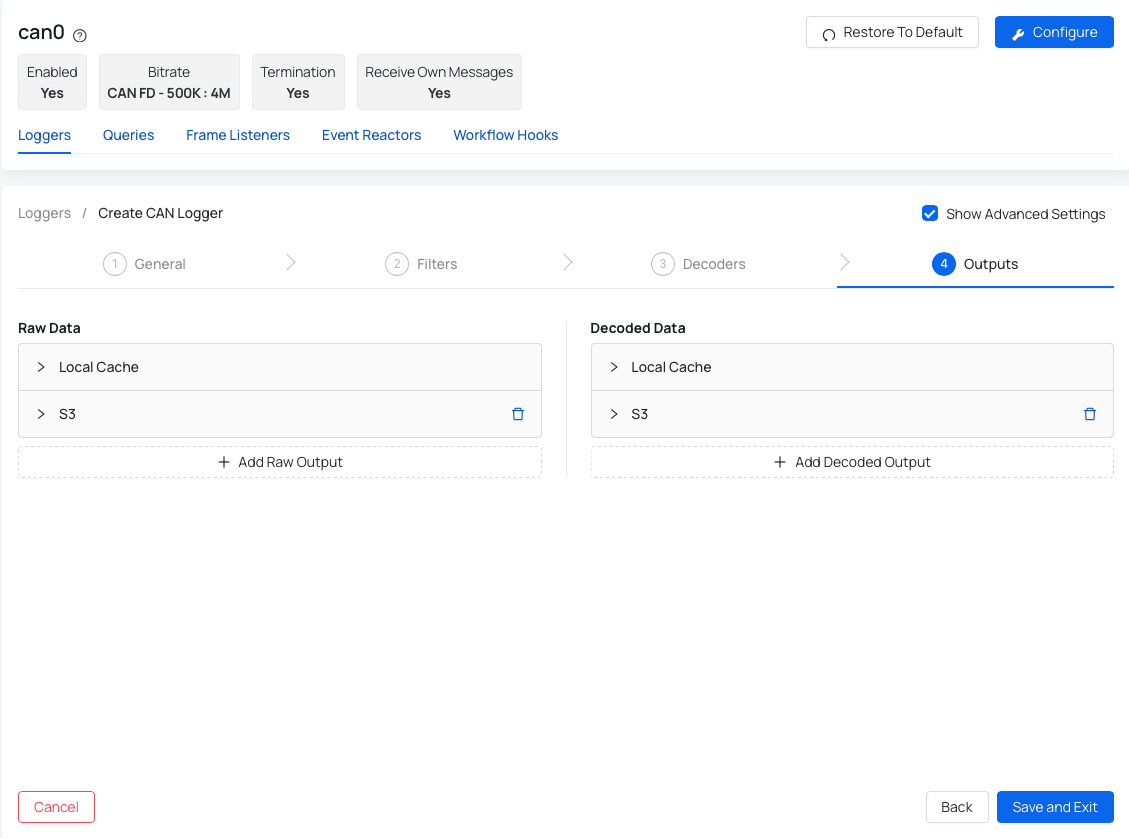
Option 1: Raw data Raw data accessible locally on the device - raw data are logged on a local disk. Logger will always log to local disk first (not possible to disable) before transferring the data to any other output. When Local Disk is running full, Disk Housekeeper is deleting these files (starting with the oldest) to free up the memory.
-
You can however configure these settings:
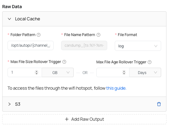
- Folder Pattern - Local folder where the output files containing raw CAN frames are saved to.
- File Name Pattern - The format string used to name the output files in a consistent manner. Raw files will be named with using this pattern. This patern includes the timestamp (year, month, day, hour, minute), and therefore every time new file is made it has the timestamp as a name.
- File Format - by default it is set to log file, however we offer a different file formats to pick from: asc, blf, csv, db and jsonl. However, there are less formats available when external dump is enabled.
- Max File Size Rollover Trigger - The maximum allowed size before rollover of the output file. In order to avoid having big files, the default size is set - this is a recommended step.
- Max File Age Rollover Trigger - The maximum allowed age before rollover of the output file.
If you want to access the files through the wifi hotspot, you can follow this guide: Accessing files via SFTP/SCP on AutoPi CAN-FD Pro device.
Raw data accessible through Amazon S3 bucket - raw data will be transferred and uploaded to a S3 bucket.
-
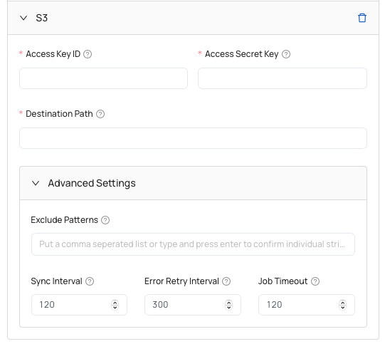
Settings for setting up AWS S3 bucket:

- Access Key ID - access key ID of AWS account to be used.
- Access Secret Key - access secret key for the AWS account.
- Destination Path - URL path to the S3 bucket container for storing output files.
- Exclude Patterns (advanced)- rule patterns used to exclude specific files or directories.
- Sync Interval (advanced)- time gap between each sync operation, specifying how often files should be synchronized automatically.
- Error Retry Interval (advanced)- period of time in seconds that the handler waits before retrying an operation after encountering an error.
- Job Timeout (advanced) - maximum duration allowed for the output handler task to run before it is automatically terminated.
Option 2: Decoded data
Decoded data accessible locally on a device - decoded data are also stored on a local disk. Logger will always log to local disk first (not possible to disable). When Disk is running full, Disk Housekeeper is deleting these files (starting with the oldest).
-
You can however configure these settings:
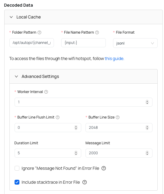
- Folder Pattern - local folder where the output files containing raw CAN frames are saved to.
- File Name Pattern - the format string used to name the output files in a consistent manner. Decoded files will be named with using this pattern. This patern includes the timestamp (year, month, day, hour, minute), and therefore every time new file is made it has the timestamp as a name.
- File Format - by default it is set to mdf4.
- Worker Interval (advanced) - time period between reading out received CAN frames from the internal buffer.
- Rollover Message Limit (advanced) - the amount of decoded CAN messages before performing rollover of the output file.
- Duration Limit (advanced)
- Message Limit (advanced)
- Ignore "Message Not Found" in Error File (advanced) - exclude message in error file when a CAN message is not found in the DBC file?
- Include stacktrace in Error File (advanced) - also include stackstrace in the error file when decoding of a CAN message fails?
If you want to access the files through the wifi hotspot, you can follow this guide: Accessing files via SFTP/SCP on AutoPi CAN-FD Pro device.
Decoded data accessible through Amazon AWS S3 bucket - decoded data will be uploaded to a S3 bucket.
- Settings that you need to set up for device to be able to upload the data to S3 bucket are these:
- Access Key ID - access key ID of AWS account to be used.
- Access Secret Key - access secret key for the AWS account.
- Destination Path - URL path to the S3 bucket container for storing output files.
- Exclude Patterns (advanced)- rule patterns used to exclude specific files or directories. Put a comma seperated list or type and press enter to confirm individual strings.
- Sync Interval (advanced) - time gap between each sync operation, specifying how often files should be synchronized automatically.
- Error Retry Interval (advanced)- period of time in seconds that the handler waits before retrying an operation after encountering an error.
- Job Timeout (advanced) - maximum duration allowed for the output handler task to run before it is automatically terminated.
How to edit CAN Logger?
Need to make changes to a CAN logger? No problem, it’s super simple. Just follow these steps:
- Go to the Devices section in the menu.
- Select the device you want to work with.
- Click on CAN Logging tab.
- Under Loggers, find the specific logger you’d like to edit.
- Click the three dots icon in the top-right corner of that logger.
- From the dropdown menu, select Edit.
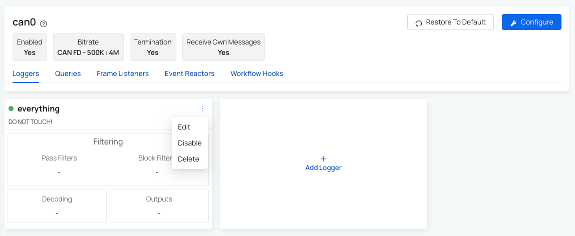
- Make your changes and save when you’re done.
Queries
Queries allow the vehicle to request specific data points at a defined frequency. You can configure an interval that determines how often the vehicle should ask for and retrieve this data.
How to create Query?
AutoPi CAN-FD Pro is supporting creation of different types of queries, including:
- OBD-II PID
- J1939 PGN
- Raw
Create OBD-II PID Query
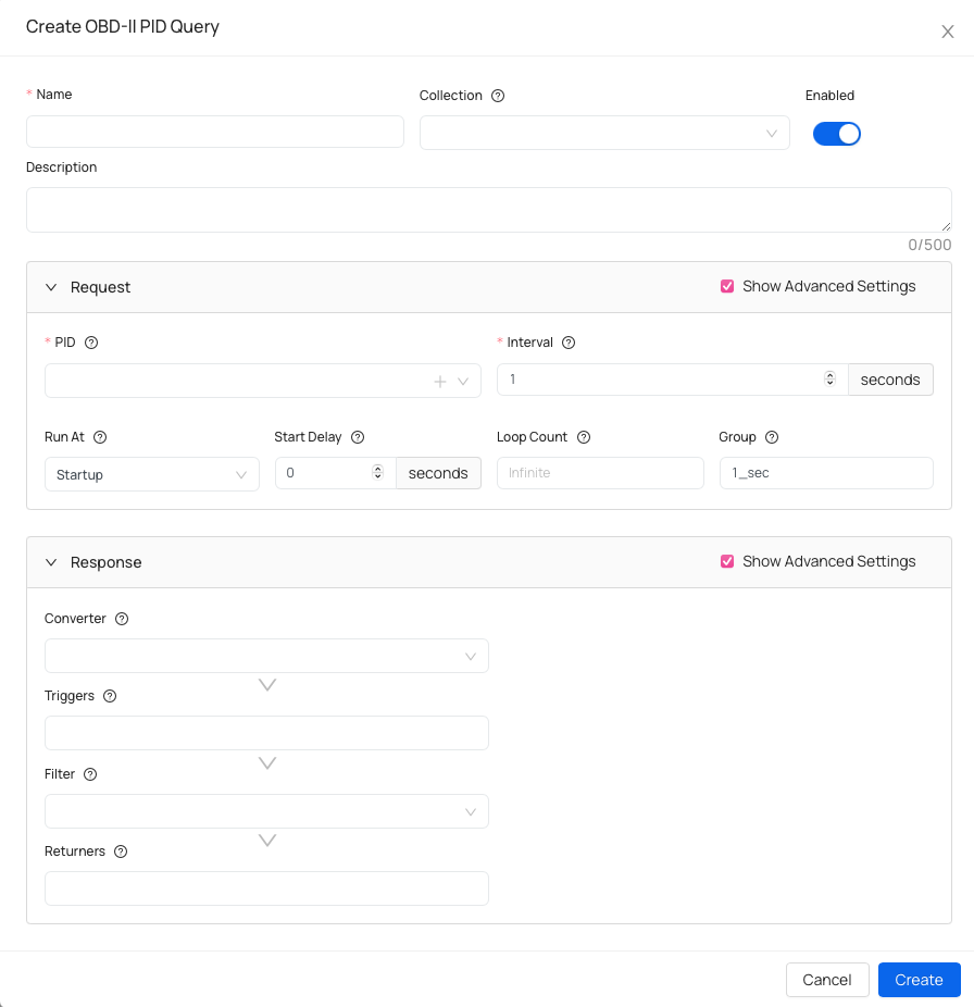
Basic information:
- Name - name your query.
- Collection (optional) - assign this query to a collection to keep related queries organized.
- Description (optional) - helpful if you want to add details about query specifications.
Request specifications
- PID - OBD-II Parameter ID
- Interval - amount of seconds between requests.
- Run At (advanced) - defines when this query runs (on startup, on ignition on, on trip start or manually).
- Start Delay (advanced) - amount of seconds before executing a query.
- Loop Count (advanced) - number of times this query will execute before stopping. Set
-1for unlimited loops. - Group (advanced) - logical group that schedules queries sharing the same execution interval.
Response specifications
- Converter (advanced) - applies a transformation to the query response.
- Triggers (advanced) - specify one or more triggers that fire events based on the query response or converter result, if specified.
- Filter (advanced) - a filter can discard unwanted results.
- Returners - especify one or more returners that deliver results to other systems or services.
Create J1939 PGN Query
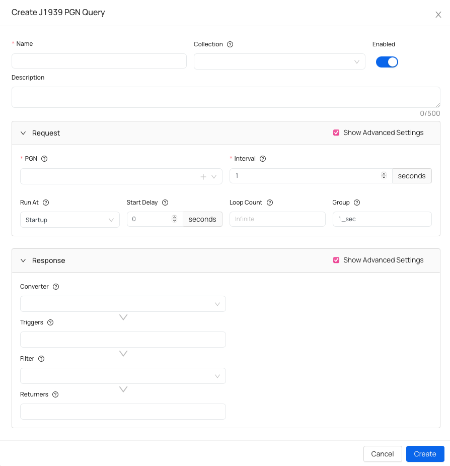
Basic information:
- Name - name your query.
- Collection (optional) - assign this query to a collection to keep related queries organized.
- Description (optional) - helpful if you want to add details about query specifications.
Request specifications
- PGN - identifier of the J1939 message (Parameter Group Number).
- Interval - amount of seconds between requests.
- Run At (advanced) - defines when this query runs (on startup, on ignition on, on trip start or manually).
- Start Delay (advanced) - amount of seconds before executing a query.
- Loop Count (advanced) - number of times this query will execute before stopping. Set
-1for unlimited loops. - Group (advanced) - logical group that schedules queries sharing the same execution interval.
Response specifications
- Converter (advanced) - applies a transformation to the query response.
- Triggers (advanced) - specify one or more triggers that fire events based on the query response or converter result, if specified.
- Filter (advanced) - a filter can discard unwanted results.
- Returners - specify one or more returners that deliver results to other systems or services.
Create Raw Query
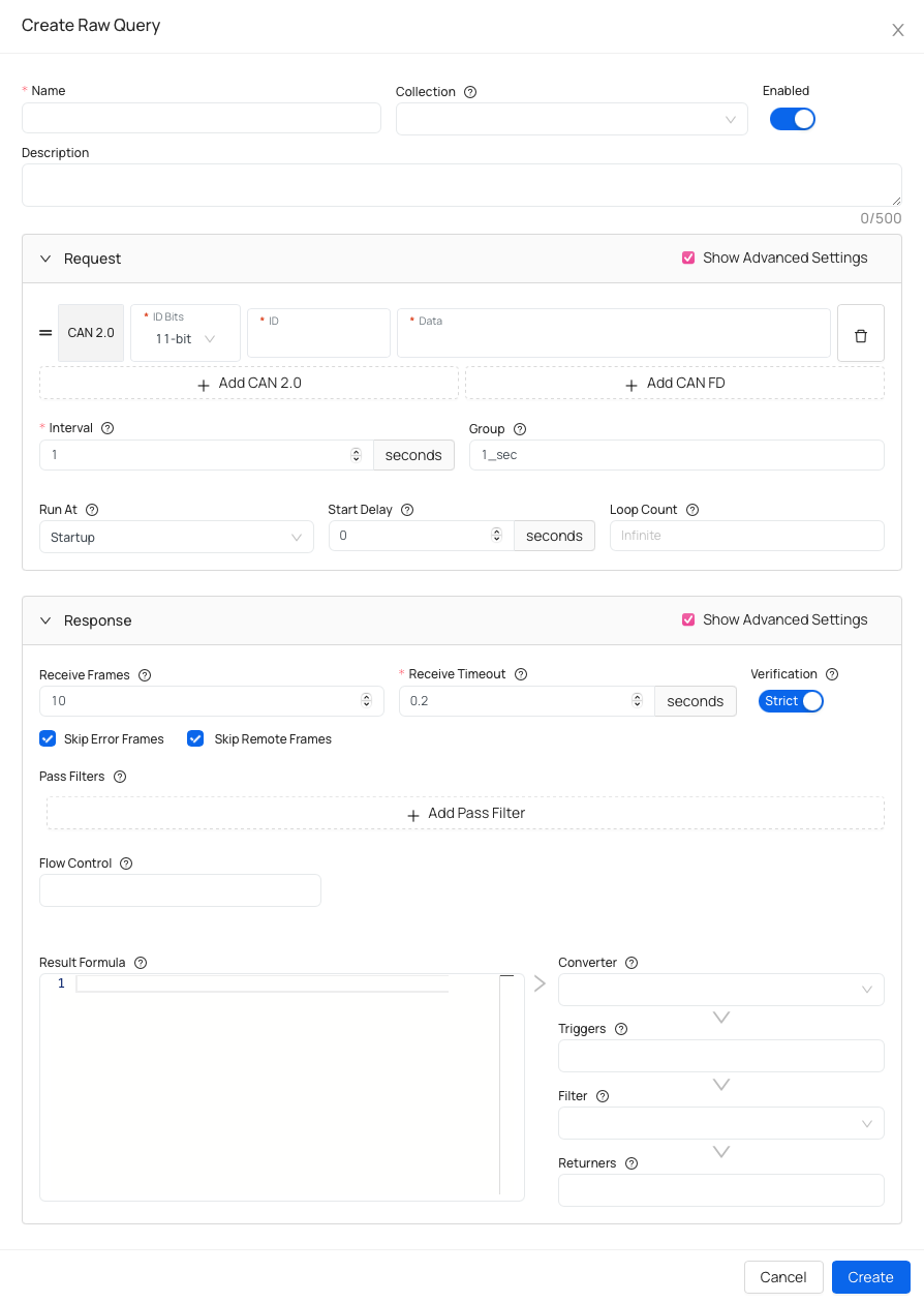
Basic information:
- Name - name your query.
- Collection (optional) - assign this query to a collection to keep related queries organized.
- Description (optional) - helpful if you want to add details about query specifications.
Request specifications
- Choose between 2 CAN protocols:
- CAN 2.0 (Standard)
- CAN FD (Extended)
- Interval - amount of seconds between requests.
- Group (optional) - logical group that schedules queries sharing the same execution interval.
- Run At (advanced) - defines when this query runs (on startup, on ignition on, on trip start or manually).
- Start Delay (advanced) - amount of seconds before executing a query.
- Loop Count (advanced) - number of times this query will execute before stopping. Set
-1for unlimited loops.
Response specifications
- Receive Frames (optional) - the specific amount of reply frames to wait for within the timeout period.
- Skip Error Frames (advanced)
- Skip Remote Frames (advanced)
- Receive Timeout - the amount of time in seconds to wait for a reply frame.
- Verification (optional) - raise an error when no reply frames are received or if the amount of expected reply messages is not met within the timeout.
- Pass Filters (advanced) - list of pass filters to use for receiving reply frames.
- Flow Control (advanced) - list of flow control ID resolvers to enable. Options are 'OBD' and 'Custom'.
- Result Formula - python code that decodes the raw byte data to a value.
- Converter (advanced) - applies a transformation to the query response.
- Triggers (advanced) - specify one or more triggers that fire events based on the query response or converter result, if specified.
- Filter (advanced) - a filter can discard unwanted results.
- Returners - specify one or more returners that deliver results to other systems or services.
Frame Listeners
The Frame Listeners are a feature that reacts to incoming CAN messages and allows you to define custom matching rules either based on frame data or Python expressions. When a match occurs, it can trigger an event or execute a custom worfklow. Frame listeners are highly customizable, giving you control over how CAN messages are processed.
How to create Frame Listener?
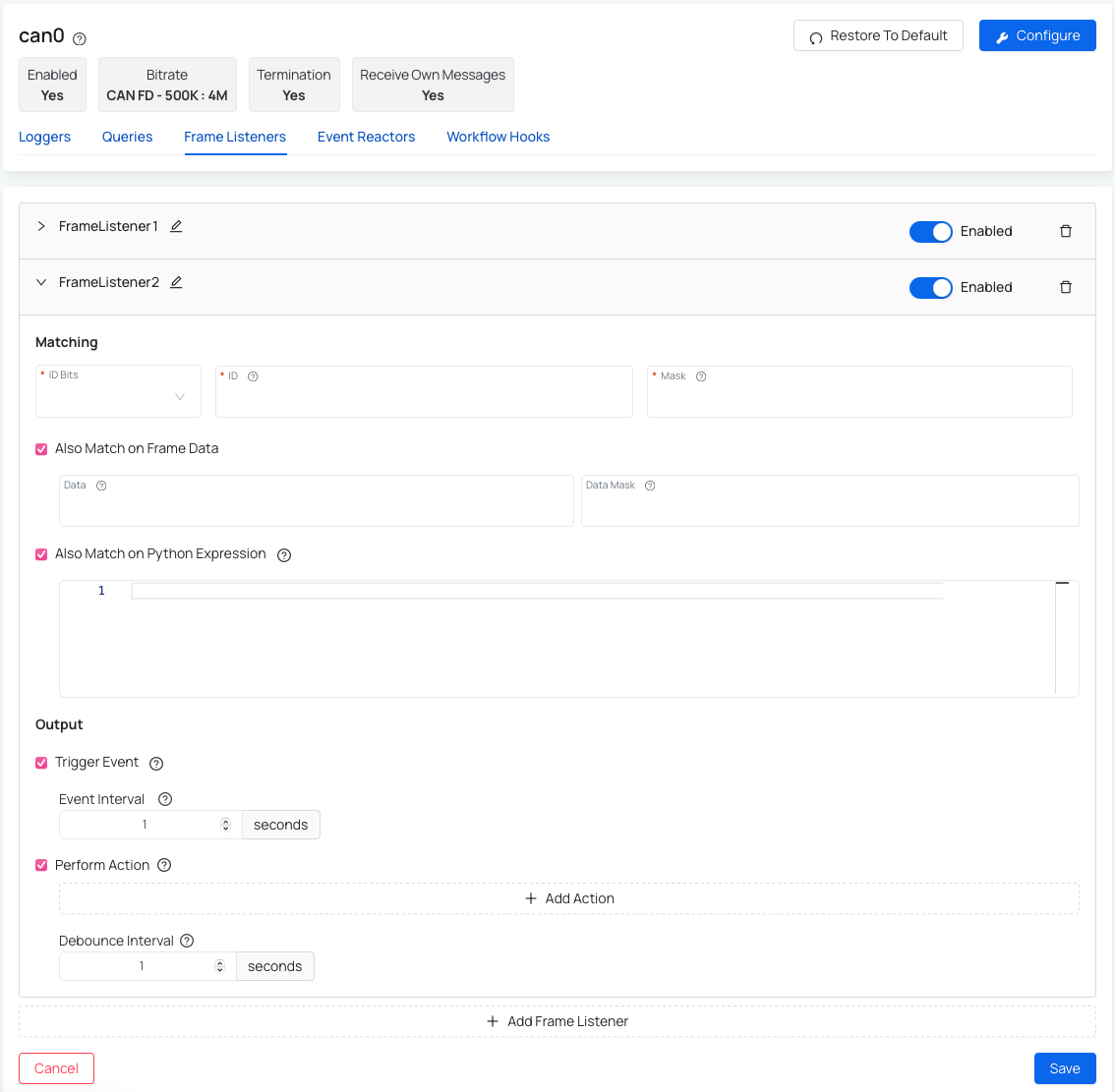
Matching part:
- ID Bits - pick between 11 and 29 bits.
- ID - arbitration ID to match against incoming frames.
- Mask - bitmask that determines whether there is a match with the specified arbitration ID. Used to match ranges or groups of IDs.
- Also Match on Frame Data - where you would need to specify Data (value to match against the data part of incoming frames) and Data Mask (bitmask that determines whether there is a match with the specified data value).
- Also Match on Python Expression - python expression which is evaluated to determine if there is a match.
Output part:
- Trigger Event - trigger an event when a match occurs. You can also specify the Event interval to further specify the minimum frequency in seconds at which workflow execution is performed.
- Perform Action - specify one or more workflows to perform on a match.
Example Use Case Imagine your AutoPi CAN-FD Pro is configured to collect only a limited set of data parameters at a low frequency (for example, once per hour). If a specific error message appears on the CAN bus, you can use a frame listener to react immediately. In this scenario, the frame listener detects the error message and triggers a custom action such as increasing logging frequency or enabling additional loggers. This allows you to capture more detailed data around the issue, making it much easier to investigate and identify the root cause.
Event Reactors
Event Reactors enable the system to react to incoming data by executing custom actions. For example, they can run a command when the device starts logging data or trigger any custom code based on defined conditions.
How to create Event Reactor?
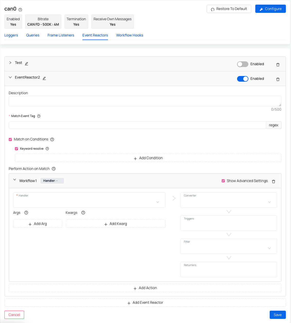
- Add Event Reactor
- Description (optional) - helpful if you want to add details about event reactor specifications.
- Match Event Tag - regular expression to match on an event tag.
- Match on Conditions (optional)- specify additional conditions that must all be met for a match to occur.
- Keyword resolve - enable resolving of keywords specified in conditions. Examples of keywords are:
$context, $event, $match, $options and $salt.
- Keyword resolve - enable resolving of keywords specified in conditions. Examples of keywords are:
- Perform Action on Match - specify one or more workflows to perform on a match (such as handler, converter, trigger, filter, returner).
Make sure you create the Workflow hooks before selecting the Event Reactor. If no hooks exist, the dropdown will be empty and you won’t be able to select one at this step. If that happens, you can still save your changes and come back later to edit and complete the configuration.
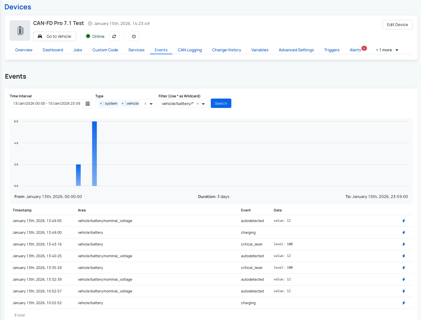
Common event types and examples
The Events functionality provides a historical overview of what has been happening on a device over time. Events capture important system and vehicle activities, giving you deeper insight into the device’s behavior and status. To view events, navigate to your Device and open the Events tab. From there, you can see the full event history and easily filter the results by a specific timeframe or by event tags to focus on what matters most.
You can find a complete list of available events and detailed descriptions in our documentation: AutoPi CAN-FD Pro events.
Some examples of commonly used events include:
- Battery events:
- For example when the battery voltage has reached a critically low level:
vehicle/battery/critical_level
- For example when the battery voltage has reached a critically low level:
- Battery Nominal Voltage events:
- For example when the AutoPi device was able to autodetect the battery nominal voltage:
vehicle/battery/nominal_voltage/autodetected
- For example when the AutoPi device was able to autodetect the battery nominal voltage:
- CAN Logging Events:
- For example when a logger is writing raw CAN frames to an output file:
vehicle/bus/<can0|can1|...>/logger/<logger_name>/writing - For example when an AWS S3 sync job has finished with success:
vehicle/bus/<can0|can1|...>/logger/<logger_name>/s3_sync/completed
- For example when a logger is writing raw CAN frames to an output file:
- Position events
- For example when the vehicle's current position is not confirmed:
vehicle/position/unknown
- For example when the vehicle's current position is not confirmed:
- Motion events
- For example when the accelerometer readings detected a sudden jolt in the device:
vehicle/motion/jolting
- For example when the accelerometer readings detected a sudden jolt in the device:
Workflow Hooks
Workflow Hooks define reusable logic that can be attached to workflows to process, modify, or react to data at specific stages. They act as building blocks that encapsulate commands, custom code, and configuration, making workflows modular and easier to maintain.
Each Workflow Hook has a defined type (handler, converter, trigger, filter, enricher, or returner) that determines its role in the workflow, along with a function (execution module) to be called. Optional arguments (args and kwargs) can be provided to customize how the function is executed.
How to create Workflow Hook?
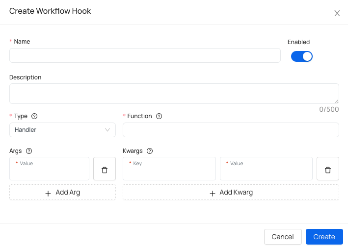
Basic information
- Name - name your workflow hook.
- Description (optional) - helpful if you want to add details about hook specifications.
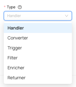
Defining the type of the worflow hook
- Type - specify the type of workflow hook, you can pick from: handler, converter, trigger, filter, enricher and returner.
- Function - refers to the command aka execution module to be called. Custom execution modules can be defined via custom code.
- Args (optional) - positional arguments passed to the command.
- Kwargs (optional) - keyword arguments passed to the command.
Advanced settings
Our newest AutoPi CAN-FD Pro device has some additional advanced settings that can be modified. These settings are namely: Can Logging (only available for AutoPi CAN-FD Pro ) and Tailscale (available not only for AutoPi CAN-FD Pro but also for AutoPi TMU CM4).
Advanced settings for Disk Housekeeper
Steps to get into advanced settings for disk housekeeper:
- Go to the Devices section in the menu.
- Select the device you want to work with.
- Click on Advanced settings.
- Click on Can Logging.
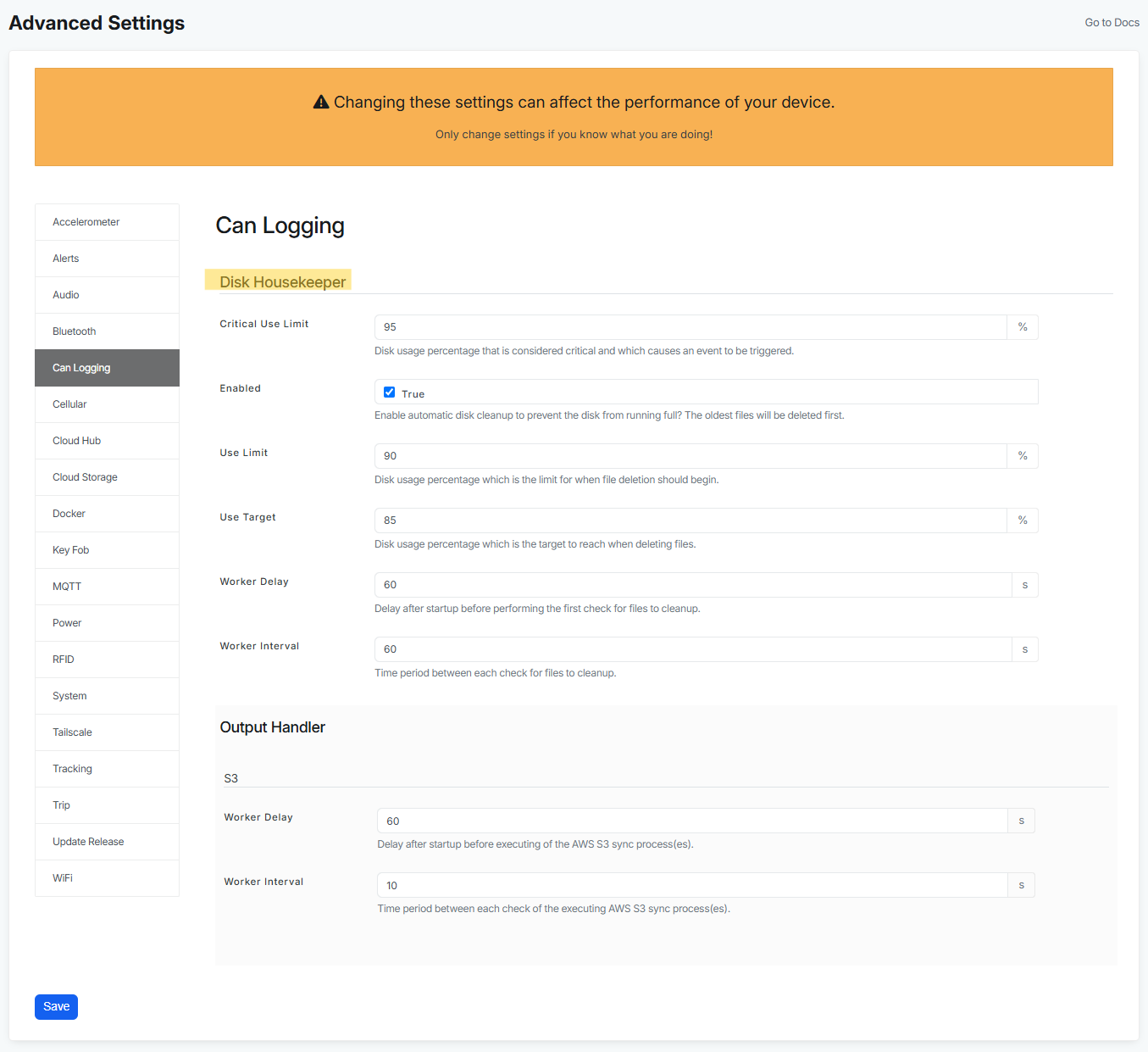
Settings for disk housekeeper:
- Critical use limit - this setting allows you to set an event based on critical use limit (user customizable). Disk usage percentage that is considered critical and which causes an event to be triggered.
- Enabled - this settings allows you to enable Disk Housekeeper, that prevents your disk from running full with old files. By clicking on True, you enable automatic disk cleanup to prevent the disk from running full. The oldest files will be deleted first.
- Use limit - disk usage percentage which is the limit for when file deletion should begin. This means that when this limit is hit or exceeded, the housekeeper starts to clean up and then it cleans up until it reaches 85% (to reach the Use Target - customizable in the setting below). And in order for you to not loose data, it takes always the oldest files first.
- Use target - disk usage percentage which is the target to reach when deleting files.
- Worker delay - represents delay after startup of the device before performing the first check for files to cleanup. This simply means that after device is woken up, it does all the neccesary functions first and Disk housekeeper is delayed by default by 60 seconds to give device enough time to postpone to a little later, the better for the performance and start up time.
- Worker interval - represent time period between each check for files to cleanup.
Every time the Disk Housekeeper deletes anything, it triggers an event that could be seen in the events section. This should help users to understand a little better what is happening on a device. We have 2 events:
system/disk_housekeeper/ordinary_purge- this event is triggered when it reaches ordinary limits (customizable in the advanced settings).system/disk_housekeeper/critical_purge- this event is triggered when it reaches critical limits (customizable in the advanced settings).
Advanced settings for Output Handler
Steps to get into advanced settings for output handler:
- Go to the Devices section in the menu.
- Select the device you want to work with.
- Click on Advanced settings.
- Click on Can Logging.
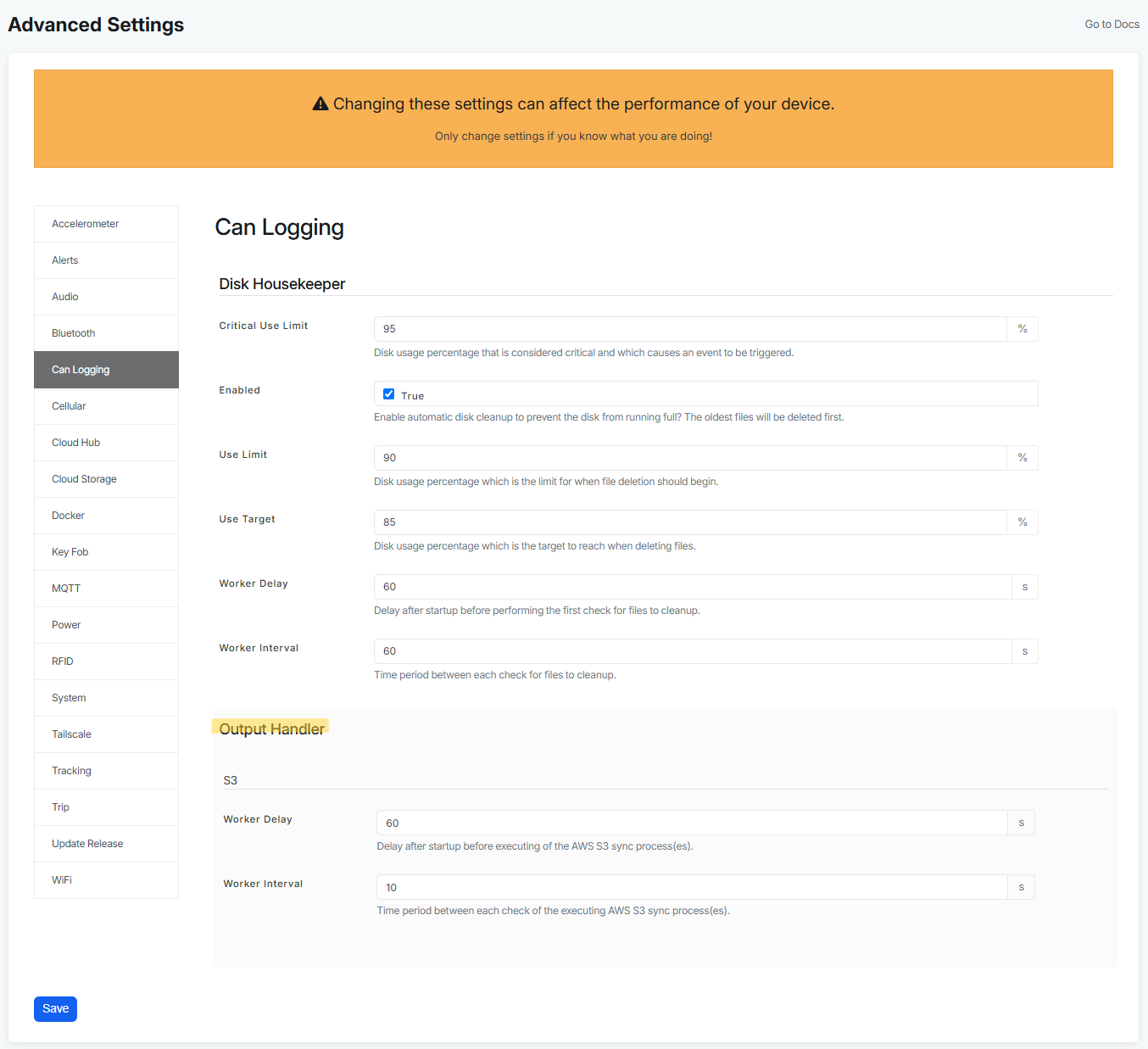
At the moment if you want to use AWS S3 Cloud storage as an output handler, you will need to fill out these fields:
- Worker delay - delay after startup before executing of the AWS S3 sync process.
- Worker interval - time period between each check of the executing AWS S3 sync process. Checking the upload job by default every 10 seconds, making sure the files are uploaded. If the job is hanging, it will close it, to ensure you won't loose any data.
Advanced settings for Tailscale
Steps to get into advanced settings for Tailscale:
- Go to the Devices section in the menu.
- Select the device you want to work with.
- Click on Advanced settings.
- Click on Tailscale.
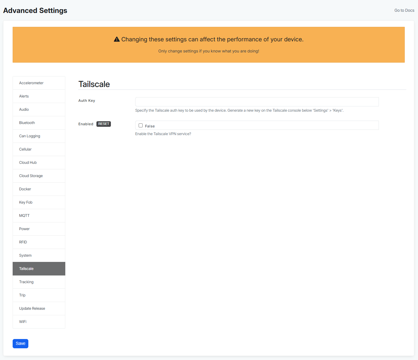
At the moment if you want to access your device remotely using Tailscale you will need to configure these fields:
- Auth Key - Specify the Tailscale auth key to be used by the device. Generate a new key on the Tailscale console below 'Settings' > 'Keys'.
- Enabled - by default this setting is not enabled, but if you want to use Tailscale, you just have to enable it here.
For more information check out this guide: How to connect to Tailscale on your AutoPi device
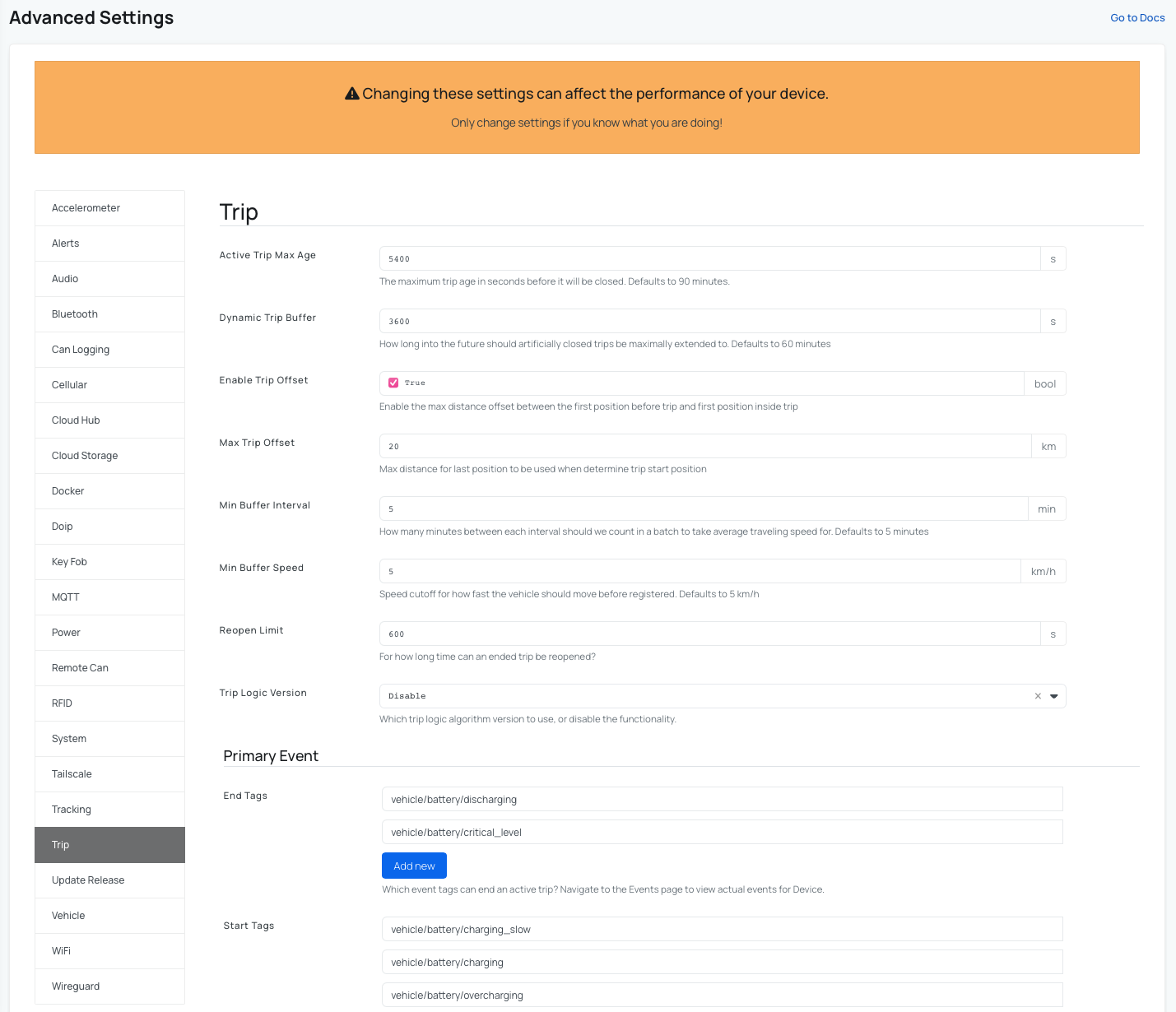
Advanced settings for Trips
The Trips feature provides detailed information about each vehicle trip, including the route displayed on a map, start and end addresses, trip duration, and distance traveled. You can also categorize trips as personal or business and export trip data when needed. For your AutoPi CAN-FD Pro device you can also tweak some extra settings under Advanced settings -> Trip.
Enable trip functionality
Steps to get into advanced settings for trips:
- Go to the Devices section in the menu.
- Select the device you want to work with.
- Click on Advanced settings.
- Click on Trip.
- Set Trip Logic Version to Improved (This is our enhanced trip detection logic, designed to provide more accurate trip mapping.).
- (Optional) Configure custom start and end event tags for your vehicle. We provide preset primary and secondary events, but if trip detection is not working correctly for your vehicle, you can modify these events to better match your use case.
Advanced settings for Vehicle
Under this tab, the AutoPi CAN-FD Pro device allows you to tweak some extra settings for Ignition Event and Trip Event.
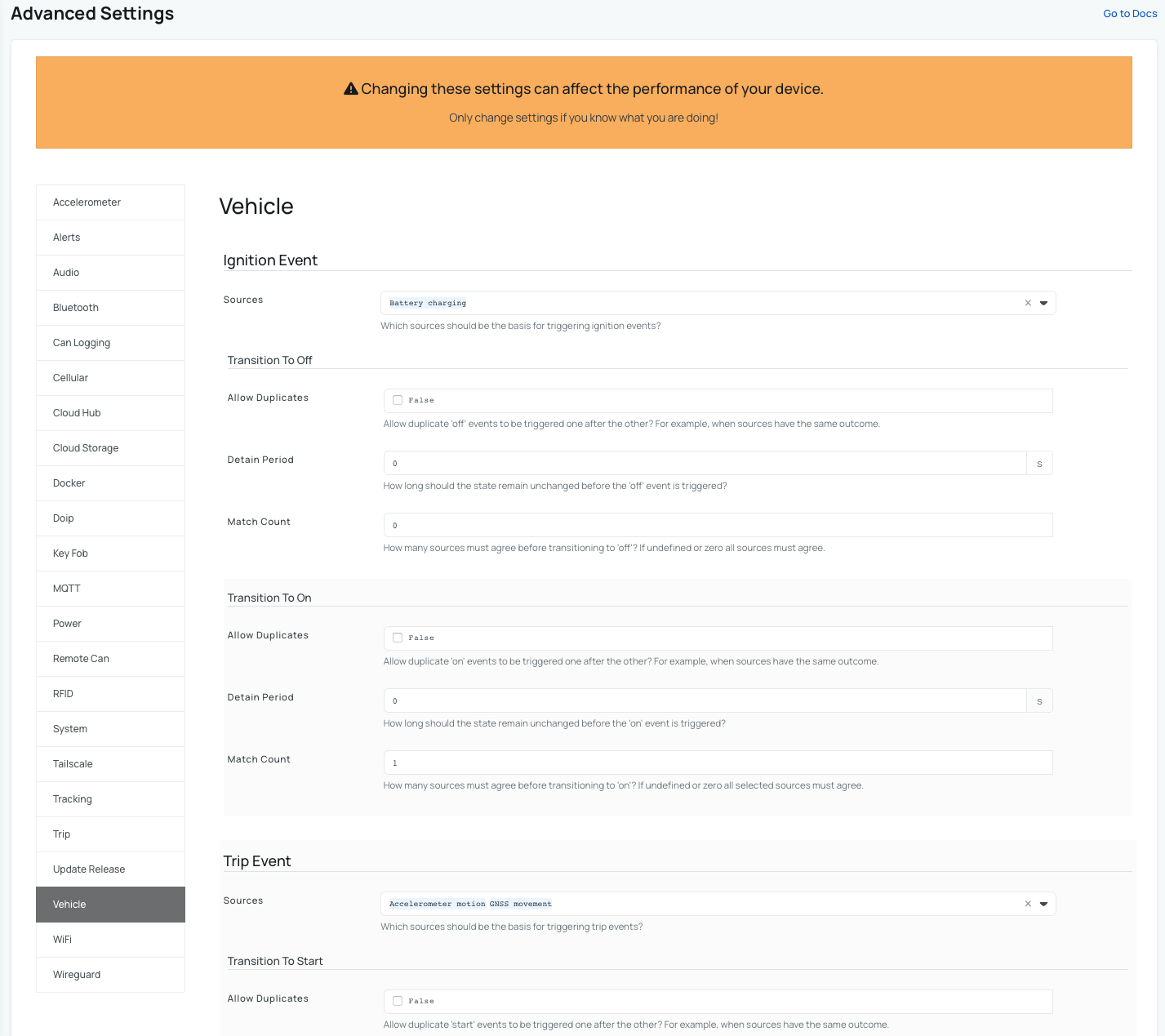
In the Trip Event section:
- Under Sources, select which data source should be used to trigger trip start and stop events.
- Adjust the Transition to Start and Transition to Stop settings to fine-tune how trips are detected.
These settings allow you to control exactly when a trip is considered active, ensuring that CAN data logging starts and stops at the appropriate times.
 Buy AutoPi device
 Compare all AutoPi devices
 Contact our sales team