Male CAN Bus Cable with Open Wires
Introduction
Do you need to connect your AutoPi device directly to a CAN bus interface?
The Male CAN Bus Cable with Open Wires allows you to connect your AutoPi device directly to CAN bus systems using open wire connections. This cable is ideal for custom installations and integration with specialized CAN bus networks. Simply match the wire colors to your target CAN bus signals and secure the connections.
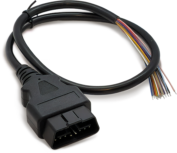
The cable features open wires for flexibility in custom configurations, and is constructed with premium materials built for reliable use.
This cable can be purchased through the AutoPi shop: Male CAN Bus Cable with Open Wires.
Specifications
| Property | Details |
|---|---|
| Connector Type | Male CAN Bus connector |
| Wire Type | 16 open wires (one wire per OBD-II pin) |
| Supported Protocols | CAN 2.0, J1939, and other OBD-II/CAN-based protocols |
| Durability | Premium materials for reliable use |
| Applications | Custom CAN bus integrations and installations |
OBD-II Pin Breakout (16 Open Wires)
| OBD-II Pin | Typical Function | Wire Color on AutoPi's Cable* |
|---|---|---|
| Pin 1 | Manufacturer specific | Brown |
| Pin 2 | SAE J1850 Bus+ (vehicle dependent) | Brown + White |
| Pin 3 | Manufacturer specific | Purple |
| Pin 4 | Chassis Ground | Mustard Yellow |
| Pin 5 | Signal Ground | Light blue |
| Pin 6 | CAN High (ISO 15765-4 / J1939) | Green |
| Pin 7 | K-Line (ISO 9141-2 / ISO 14230-4) | Black |
| Pin 8 | Manufacturer specific | Black + White |
| Pin 9 | Manufacturer specific | Red + White |
| Pin 10 | SAE J1850 Bus- (vehicle dependent) | White |
| Pin 11 | Manufacturer specific | Yellow |
| Pin 12 | Manufacturer specific | Pink |
| Pin 13 | Manufacturer specific | Grey |
| Pin 14 | CAN Low (ISO 15765-4 / J1939) | Green + White |
| Pin 15 | L-Line (optional / vehicle dependent) | Blue |
| Pin 16 | Battery Power (VBat) | Red |
*Color mapping can vary by cable production batch. Always verify each wire with a multimeter/continuity test before connecting to vehicle power or bus lines.
Connection Guide
When connecting the open wires:
- Identify the exact wire-to-pin mapping for your cable batch.
- Connect power and ground first (OBD-II Pin 16 and Pin 5).
- Connect CAN High and CAN Low next (OBD-II Pin 6 and Pin 14).
- Connect any remaining lines only if required by your protocol.
Ensure all connections are secure and properly insulated. Incorrect connections can damage your AutoPi device or target system. Verify wire connections against your system's CAN bus documentation before powering on.
 Buy AutoPi device
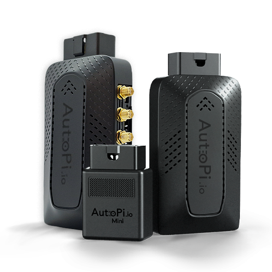 Compare all AutoPi devices
 Contact our sales team