Introduction
AutoPi power management controls when the device is awake, sleeping, or hibernating. These states allow the device to collect and upload data while protecting the vehicle's battery.
This guide explains each power state, what causes the device to change states, and how the status LEDs indicate its current state. To configure when the device sleeps, see Sleep Timers.
For device-specific power cycle, LED, and button behavior, see LED and Button on AutoPi TMU CM4 Devices or LED and Button on AutoPi CAN-FD Pro Devices.
How Power Management Works
Power management has two layers:
- Low-level power management controls the hardware states and wake triggers through the Smart Power Management (SPM) system. To learn more about the underlying service, see SPM Manager.
- High-level power management uses AutoPi Core commands, settings, and events to decide when the device should sleep or hibernate.
Power Cycle
The device uses three main operating states:
| State | Description | How the Device Leaves the State |
|---|---|---|
| On | The device collects data, runs configured tasks, and communicates with AutoPi Cloud. | A sleep timer expires, or a hibernation threshold is reached. |
| Sleeping | The Raspberry Pi is powered off for a configured interval to reduce power consumption. | A wake timer expires, or a configured source such as a voltage change, the modem, or the accelerometer triggers a wake-up. |
| Hibernating | Almost all components are powered off to protect a low vehicle battery. | The STN chip detects that the voltage has risen above the configured wake threshold. |
When the Vehicle Is Parked
When you connect the device while the vehicle's engine is off, the typical cycle is:
- The device boots and connects to AutoPi Cloud.
- The device creates a sleep timer. The default timer is five minutes, but the configured value may differ.
- When the timer expires, the device sets a hardware wake timer and attempts to upload pending data.
- The device shuts down and enters the
Sleepingstate. - When the wake interval expires, the device boots again. If the vehicle is still inactive, the device creates another sleep timer and repeats the cycle.
This periodic wake-up allows the device to process tasks and upload data without remaining on continuously. See Sleep Timers to configure the awake period and sleep interval.
When the Vehicle Starts
If the device is sleeping when the engine of a standard internal combustion engine (ICE) vehicle starts, the typical sequence is:
- The STN chip detects that the vehicle's battery voltage has risen above the configured wake threshold.
- The STN chip sends a wake signal, and the device boots.
- The device detects CAN bus traffic and RPM data.
- The RPM data triggers the
vehicle/engine/runningevent. - The device clears its sleep timers and prevents new timers from being set while the vehicle is running.
If the device is already on when the vehicle starts, it remains on and clears its sleep timers without rebooting.
Vehicles that do not provide standard OBD-II engine data may require additional configuration to keep the device awake while driving. For electric vehicles, see Configure the Power Cycle for Electric Vehicles.
When the Battery Voltage Is Low
Hibernation protects the vehicle's battery when its voltage falls too low. You can configure two hibernation thresholds under Devices > select a device > Advanced Settings > Power:
| Setting | Behavior |
|---|---|
| Critical Level | Starts a graceful shutdown. Before entering hibernation, the device attempts to upload pending data and report the event to AutoPi Cloud. |
| Safety Cut-Out | Immediately cuts power to prevent further battery drain. AutoPi Cloud receives a notification after the device comes back online. |
The device can report a critical-level shutdown to AutoPi Cloud only when it has an internet connection. While the battery voltage remains above both thresholds, the device continues its configured wake-and-sleep cycle.
Status LEDs
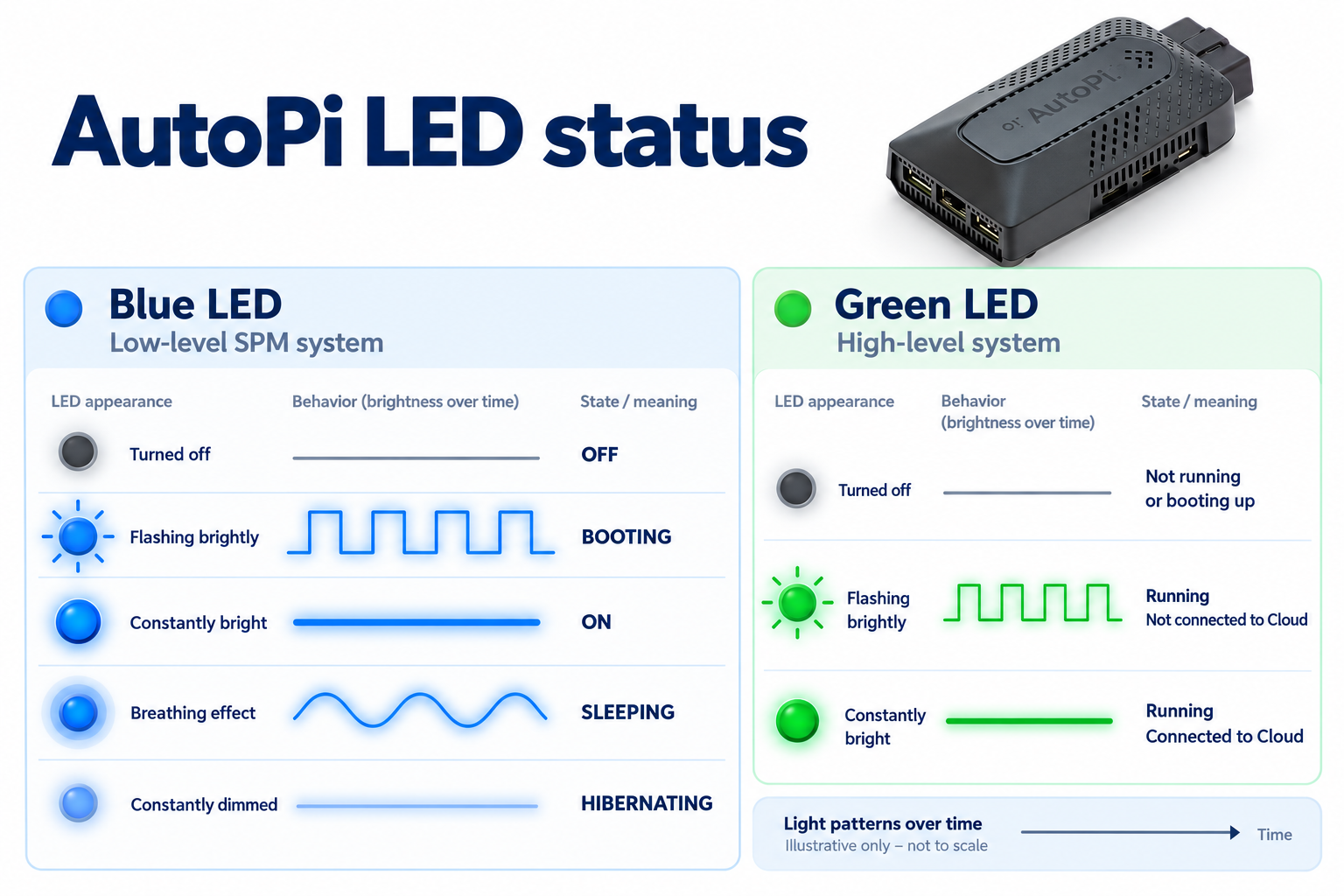
The status LEDs provide a quick visual indication of the device's current power state and connection to AutoPi Cloud.
This guide and the LED states below apply only to AutoPi TMU CM4/CAN-FD Pro devices. For information about the LED indicators on AutoPi Mini devices, see LED Lights of an AutoPi Mini Device.
Blue LED
The blue LED shows the state of the low-level SPM system.
| LED State | Description |
|---|---|
| Off | The SPM system is off. |
| Bright flashing | The SPM system is booting. |
| Constant bright light | The SPM system is on. |
| Breathing effect | The SPM system is sleeping. |
| Constant dim light | The SPM system is hibernating. |
Green LED
The green LED shows the state of the high-level power management system and its connection to AutoPi Cloud.
| LED State | Description |
|---|---|
| Off | The system is not running or is still booting. |
| Bright flashing | The system is running but is not connected to AutoPi Cloud. |
| Constant bright light | The system is running and connected to AutoPi Cloud. |
For LED light indicators on the AutoPi Mini device, see LED Lights of an AutoPi Mini Device.
 Shop AutoPi devices
 Compare devices
 Contact sales
 Contact support