Connection overview
Connectivity#
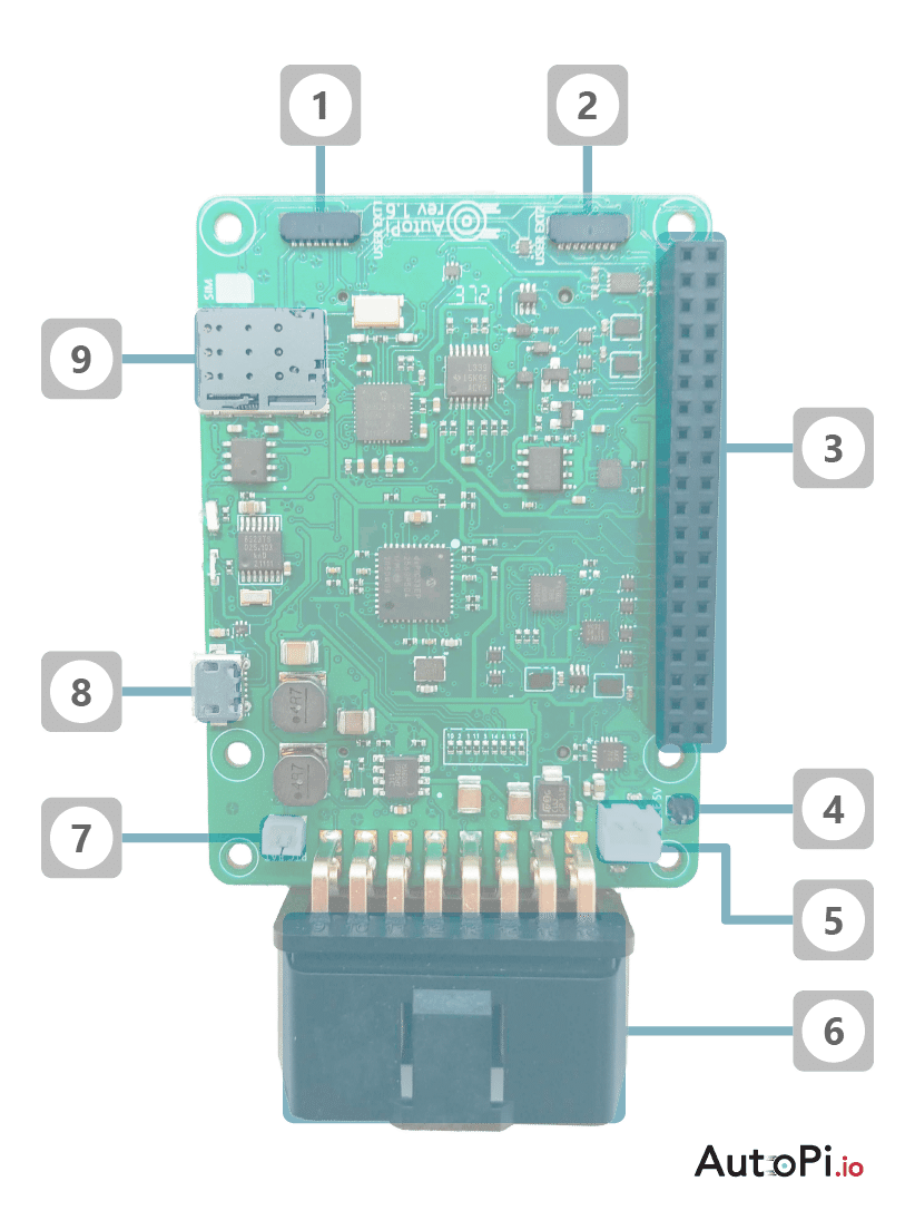
Front side#
This diagram shows the 3rd generation frontside connections possibilities
- USER EXT 1
- USER EXT 2
- GPIO pins for RPi and external connections
- GPIO Jumper to always force 5V on the RPi
- JST connector for external speaker
- OBD-II connector to the vehicle
- RTC battery connector
- Micro USB connectors for external use
- SD card slot
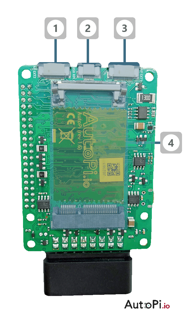
Back side#
This diagram shows the 3rd generation backside connections possibilities
- AP EXT2 - BLE module connector
- Upstream USB connector to RPi
- AP EXT1 - OBD2 pass-through connector
- Modem slot
Pinouts#
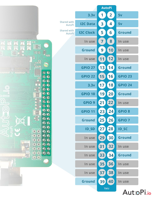
GPIO Pins#
This image is an overview of the GPIO pinout of the 3rd generation (TMU) AutoPi.
Pins marked with "in use" cannot be used for anything else. This will interrupt the functionality of the AutoPi. This I2C bus is used by the AutoPi, but can be shared with other devices.
All other pins are free and their functionality follows that of the Raspberry Pi.
note
If you'd like to discuss this topic with us or other fellow community members, you can do so on our community page dedicated for this guide: AutoPi GPIO Pinout
AutoPi Extension Port 1#

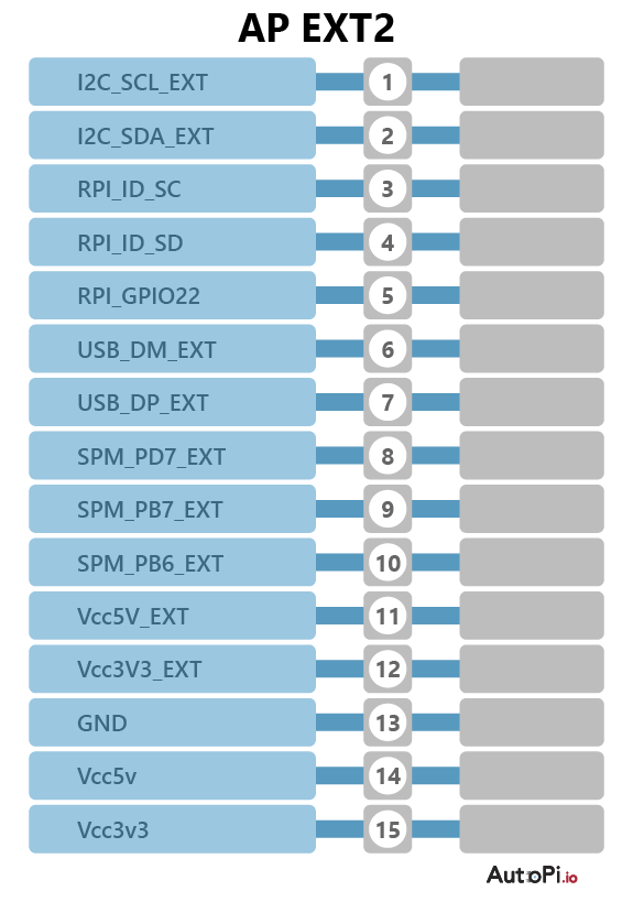
AutoPi Extension Port 2#
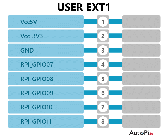
User Extension Port 1#
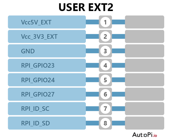
User Extension Port 2#