Getting Started
This guide will show how to retrieve data from a vehicle supporting the J1939 protocol. To read more background information about J1939 please see the blog post: J1939 Explained
Preconditions
Before proceeding the AutoPi device must be:
- Connected to the vehicle with an appropriate OBD-II adapter cable that connects the vehicles two J1939 CAN bus wires to pin 6 (high) and 14 (low) of the OBD-II connector on the AutoPi device. If you are missing an adapter cable for your specific vehicle please contact sales@autopi.io.
- When initially inserting the device, make sure that the vehicle is powered off.
- Powered on and online in the AutoPi Cloud at https://my.autopi.io.
- Also the ignition of the vehicle must be turned on to ensure the J1939 CAN bus is active.
Determining the CAN Bus protocol
First step is the determine the CAN bus protocol used for the connected vehicle (if you dont already know it). A few steps is required here:
- Remove all existing loggers on the device (make sure the changes are synced to the device). This can be done here: https://my.autopi.io go to Devices > Select Device > Loggers. You want to remove these, so that they dont interfere with the CAN Bus already.
- Remove all existing CAN busses on the vehicle. From the same page click the Settings button in the top right corner. Click the Vehicles Editor and remove the CAN busses configured in the bottom of the popup.
- Configure the vehicle for 24V operation (if its a 24V truck). You can do this on the vehicles editor page that you are add, by clicking the Nominal Voltage dropdown.
- You are now set to start the testing for the right CAN Bus configuration.
You need to make sure the device is powered on, have good internet connection and that the engine of the vehicle is running. You can do so by following these steps:
- From terminal in the right hand side screen, run the following command:
test.ping
It should return true if the device is online and connected to the Cloud.
- Again from the terminal run the following command:
obd.battery
This command command will return the Voltage of the Auxilirary battery in the vehicle. If its a 24V type of battery you should see a value somewhere between 25-28V. If its close to 25V it means the engine is not running. If its closer to 28V it means the engine is running and ECU's are powered up. A good indicator is a value above 26.5V.
With these checks passed you can now continue to find the protocol and baudrate settings. With the vehicle's engine running, first try to listen to passive CAN traffic. One of these commands should show some data (raw). Once you find which command returns data, note down the protocol and baudrate for this vehicle:
  - obd.monitor duration=5 verify=False protocol=32 baudrate=500000
  - obd.monitor duration=5 verify=False protocol=32 baudrate=250000
  - obd.monitor duration=5 verify=False protocol=32 baudrate=125000
  - obd.monitor duration=5 verify=False protocol=31 baudrate=500000
  - obd.monitor duration=5 verify=False protocol=31 baudrate=250000
  - obd.monitor duration=5 verify=False protocol=31 baudrate=125000
  - obd.monitor duration=5 verify=False protocol=52 baudrate=500000
  - obd.monitor duration=5 verify=False protocol=52 baudrate=250000
  - obd.monitor duration=5 verify=False protocol=52 baudrate=125000
  - obd.monitor duration=5 verify=False protocol=51 baudrate=500000
  - obd.monitor duration=5 verify=False protocol=51 baudrate=250000
  - obd.monitor duration=5 verify=False protocol=51 baudrate=125000
To determine whether any of the raw data is J1939, you can do 1 of 2 things:
- Check on the Cloud whether there is any data coming in. Note, that you would only be able to see this if the protocol configuration of the device matches that of the vehicle.
- Look for the EEC1 frame. If the vehicle supports J1939, it will almost certainly have this. In the data returned by the monitor command, look for a frame where the 3th to 6th characters are
F004. For example, if the full frame is18F0040012AB331288112244, you can seeF004at the beginning.
Determining if the vehicle responds to J1939 VIN queries:
If you've found the protocol, baudrate combination which works, use the same combination to check for the VIN query. Run the following command. It should return the VIN string for the vehicle:
obd.query vin mode=FEEC pid=x00 header=18ea00f9 formula='str(message.data)' verify=false force=true protocol=<PROTOCOL> baudrate=<BAUDRATE>
Check for Broadcast Data via the CAN Bus sniffer
As most J1939 messages are broadcast we start by checking if we can see any data on the CAN bus.
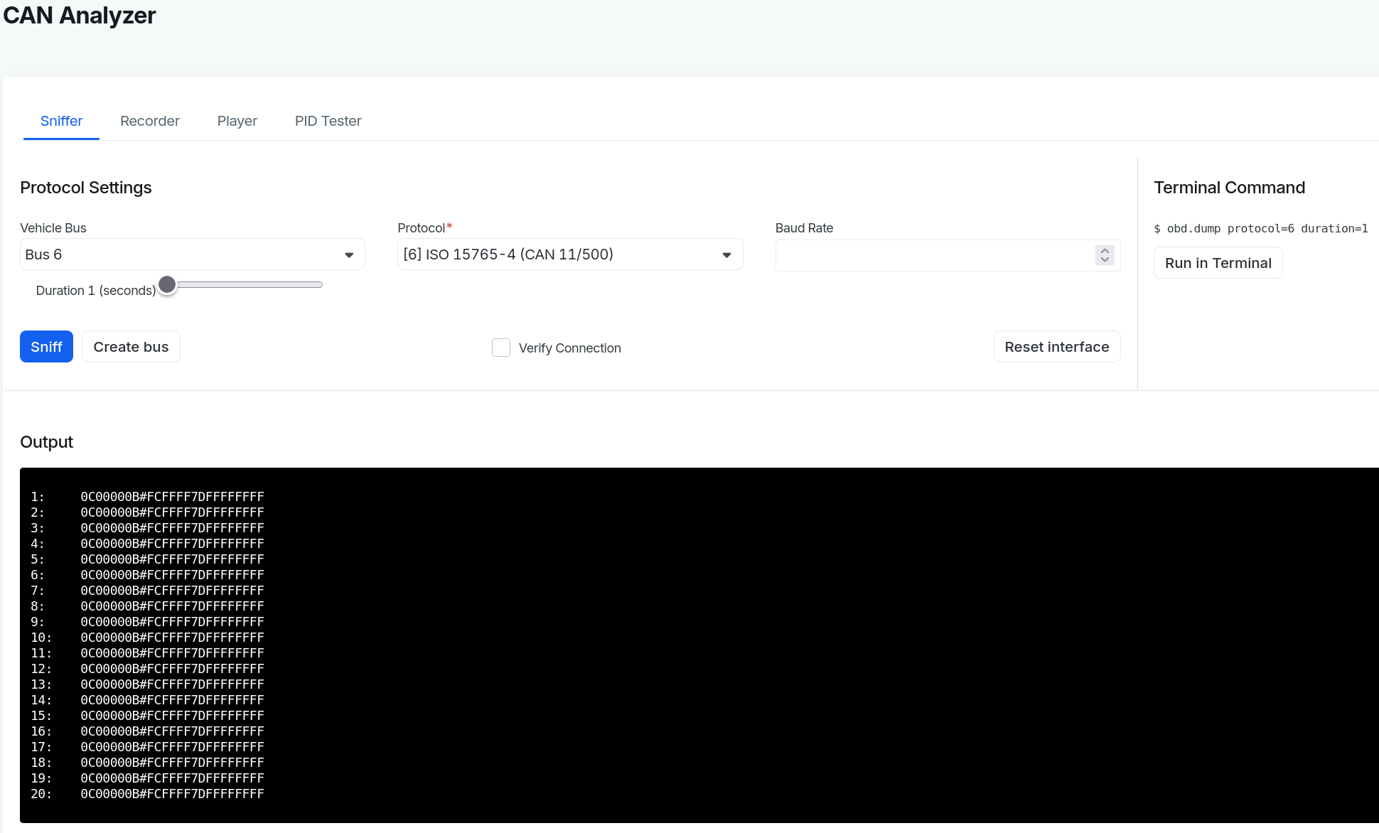
On https://my.autopi.io go to Devices > Select Device > CAN Analyzer > Sniffer.
Select one of the following J1939 protocols that fits your vehicle in regards to 11bit or 29bit header:
[41] J1939 (11bit, 250kbps)[42] J1939 (29bit, 250kbps)
Optional: Change the baud rate if predefined value of 250000 is incorrect. 500000 is a typical alternative.
Click the Sniff button to start recording CAN messages sent on the J1939 bus. An example of a recording result is shown in below screenshot.
The start and end of the recording are indicated audibly with loud beep sounds played by the AutoPi device.
Example:
If no data is returned, try:
- Change the protocol and/or baud rate combinations.
- Increase the recording duration from default
1to10seconds. - Continue to the next section describing how to query for data.
Query for Data via PID tester tool
Some data is only available on request. This means a J1939 request message must be sent in order to get a data response. This can be done using the PID tester tool.
In the CAN Analyzer select the PID Tester tab.
First the J1939 protocol and baud rate must be specified in the same way as described previously.
Next the J1939 request message must be specififed. It consists of a header and a data part.
Header:
18 EA 00 F9is broken down into:
18contains priority of 6.EA 00is PGN 59904 (Request PGN).F9is source address 249 (Service Tool).Data:
00 C1 00is the specific PGN that is requested. In this example PGN 49408 (Diagnostic Readiness 2).
Example:
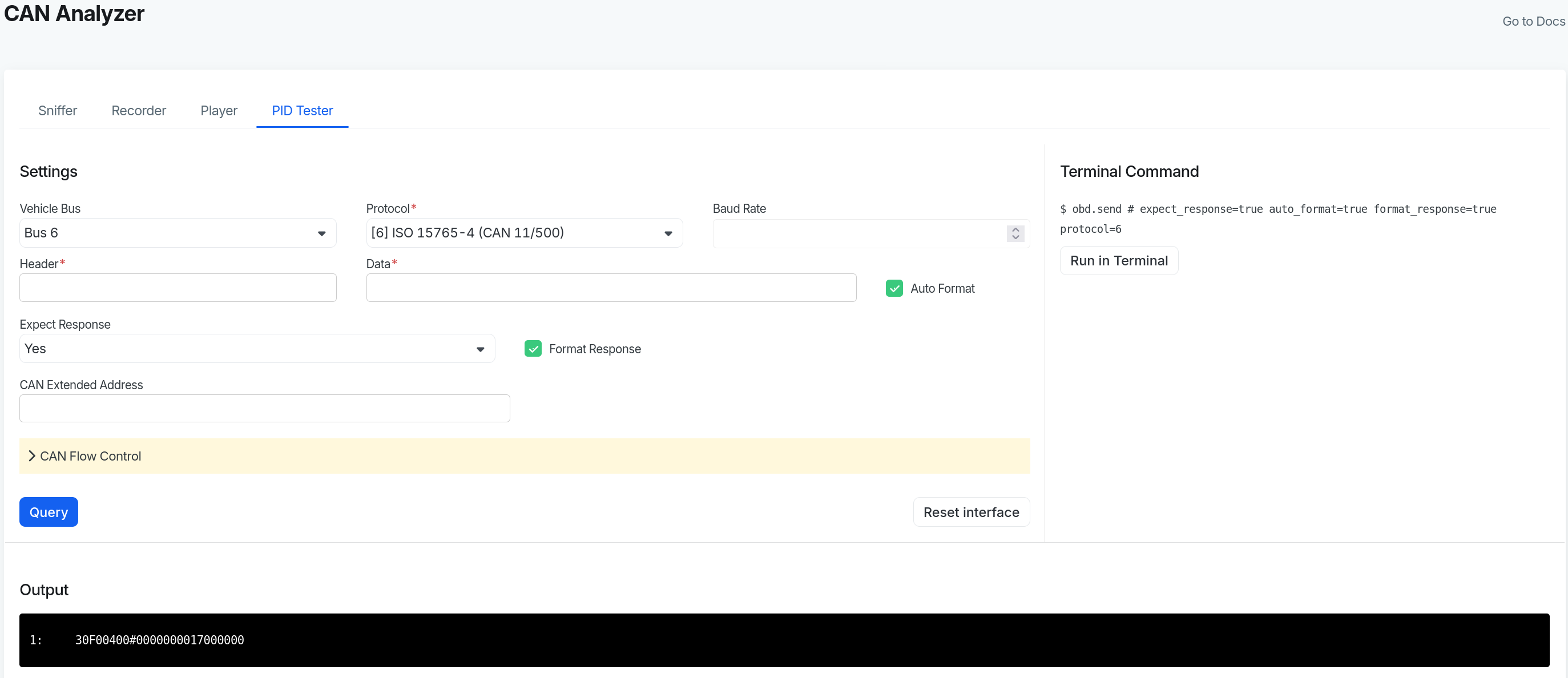
In above screenshot we query PGN 61444 (Electronic Engine Controller 1) which among other values contains SPN 190 (Engine Speed).
Register Vehicle Bus
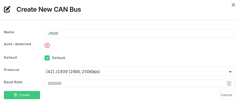
Once a J1939 bus has been identified and tested, it is recommended to register it on the vehicle's profile.
Go to Devices > Select Device > Settings > Vehicles Editor and click on Create button below CAN Buses. Fill in the relevant values for name, protocol and baud rate.
Example:
Register PID for Request PGN
This section may be skipped if you only receive broadcast J1939 messages. But if you need to query for a specific PGN it is recommended to register the request PGN as a PID in the OBD Library. It can then later be used to easily set up loggers.
Go to OBD Library > Create > PID.
Enter the informations previously verified using the PID Tester.
Example:
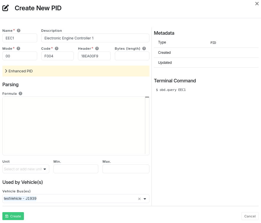
PID Details
Name: Short name of the PGN requested.
Description: Optional description of the PGN requested.
Mode: Hexadecimal value
00is specified here.Code: The hexadecimal representation of the requsted PGN number 61444 (Electronic Engine Controller 1).
Header: The header to request a PGN:
18contains priority of 6.EA 00is PGN 59904 (Request PGN).F9is source address 249 (Service Tool).
It is recommended to specify how many messages/frames are expected to be returned by the query. This is done by unfolding the section Enhanced PID and entering the number of messages under Frames. This helps reduce the total query time (better performance) because the waiting timeout for the last message is skipped.
Used by Vehicle(s)
Vehicle Bus(es): Specify which bus(es) the PID is to be associated with. The previously created J1939 bus is selected.
Decode Messages (with DBC file)
After receiving the raw J1939 CAN messages they must be decoded to get the actual measurement values. This can be done using the built-in CAN database functionality.
The CAN database contains definitions of how the individual CAN messages are structured. Each CAN message can consist of one or more CAN signals, each of which typically contains a single measurement value (eg. temperature, speed, RPM or the like).
As an exmaple, the J1939 PGN 61444 (Electronic Engine Controller 1) contains 8 SPNs in total. It can be mapped to a CAN message with 8 CAN signals as shown below.
PGN 61444 (Electronic Engine Controller 1)                            --->  CAN message
  SPN 899 (Engine Torque Mode)                                        --->    CAN signal #1
  SPN 899 (Engine Torque Mode)                                        --->    CAN signal #2
  SPN 4154 (Actual Engine - Percent Torque)                           --->    CAN signal #3
  SPN 512 (Driver's Demand Engine - Percent Torque)                   --->    CAN signal #4
  SPN 513 (Actual Engine - Percent Torque)                            --->    CAN signal #5
  SPN 190 (Engine Speed)                                              --->    CAN signal #6
  SPN 1483 (Source Address of Controlling Device for Engine Control)  --->    CAN signal #7
  SPN 1675 (Engine Starter Mode)                                      --->    CAN signal #8
  SPN 2432 (Engine Demand – Percent Torque)                           --->    CAN signal #9
When all (or only a few selected) CAN messages have be defined they will need to be synchronized to the AutoPi device and stored in the form of a DBC file. The synchronization is handled automatically by to AutoPi Cloud management system. Using this DBC file, the AutoPi device can decode raw CAN messages into readable measurement values. The decoded data can then be uploaded to the AutoPi Cloud, stored locally or sent to any custom endpoint.
Create Mapping
To create a mapping for a CAN message to be be decoded go to OBD Library > Create > CAN.
Example:
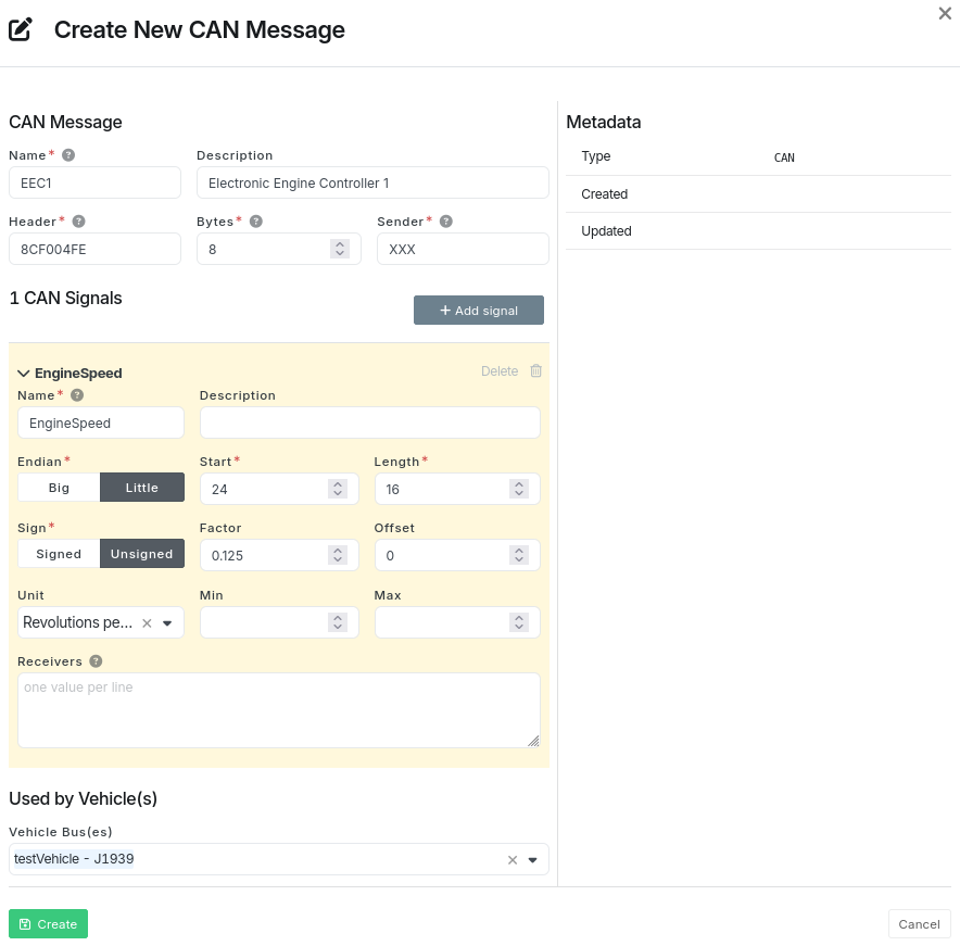
In above screenshot, we register a CAN message mapping for PGN 61444 (Electronic Engine Controller 1):
CAN Message
Name: Short name to identify the CAN message.
Description: Optional description of the CAN message.
Header: CAN message header for PGN 61444:
8Ccontains priority of 6 but has no actual significance.F004is the hexadecimal representation of PGN number 61444.FEis source address 254 (Null Address) but has no actual significance.Bytes: 8 is the number of data bytes that the CAN message contains.
Sender: Identifier of the ECU that sent the CAN message. Enter
XXXor similar if unknown.
CAN Signal #1
In the above screenshot we only show how to map SPN 190 (Engine Speed) but the procedure the same when adding more.
Name: Short name to identify the CAN signal.
Description: Optional description of the CAN signal.
Endian: Sequence of bytes is little-endian - least significant bits first.
Start: Bitwise start index of the CAN signal value within the data part of the CAN message. When it comes to big-endian indexing is straightforward, but for little-endian it is more complex.
Length: Bit length of the CAN signal value.
Sign: Unsigned integer value - no negative values.
Factor: A factor of
0.125to be multiplied by the value in order to get the actual measurement value.Offset: No offset to be added to the value.
Unit: Unit of the value is RPM (Revolutions per minute).
Min: The maximum possible value is undefined.
Max: The minimum possible value is undefined.
Receivers: Identifiers for ECUs that use the signal value.
Used by Vehicle(s)
Vehicle Bus(es): Specify which bus(es) the CAN message is to be associated with. The previously created J1939 bus is selected.
Sync DBC File
After the CAN message has been created, it must be synchronized to the AutoPi device. This is done in the same way as all other changes; applied immediately on request if the device is online or queued and applied the next time the device is back online.
When synchronizing, the CAN messages are stored in one or more DBC files located on the file system below the path:
/opt/autopi/obd/can/db/protocol_<ID>.dbc
A separate DBC file is created on the device for each associated vehicle bus protocol.
In the above example, protocol [42] J1939 (29bit, 250kbps) is used. Therefore, the synchronized DBC file will be found at: /opt/autopi/obd/can/db/protocol_42.dbc
Test CAN Converter
To easily test CAN message conversion with a DBC file, the following terminal command can be executed. It performs a single workflow that queries a PGN and then converts the raw response message using the DBC file.
obd.manage run handler="query" \
args="['EEC1']" \
kwargs='{"mode": "00", "pid": "F004", "header": "18EA00F9", "force": true}' \
converter="can"
Example:

Command Breakdown
>_**obd.manage**_ is the [command](/core/commands/core-commands-obd/#obdmanage) to execute.
>
>_**run**_ a [workflow](/core/services/core-services-intro/#workflows) directly.
>
>_**handler="query"**_ specifies the handler of the workflow to be called.
>
>_**args="['EEC1']"**_ specifices the arguments of the handler. The value consists of an embedded JSON array.
>
>_**kwargs={{"mode": "00", "pid": "F004", "header": "18EA00F9", "force": true}}**_ specifices the keyword arguments of the handler. The value consists of an embedded JSON dictionary.
>
>_**converter="can"**_ specifies a converter in the workflow to be called after the handler. Here we use the [CAN](/core/services/core-services-obd-manager/#can) converter.
Setup Loggers
To receive the J1939 data in the Cloud, loggers must first be set up on the device. Go to Device > Loggers and create loggers for the respective PIDs and or CAN messages. After a logger has been created, it must be synchronized to the AutoPi device, just like any other change.
 Buy AutoPi device
 Compare all AutoPi devices