Using the HAT
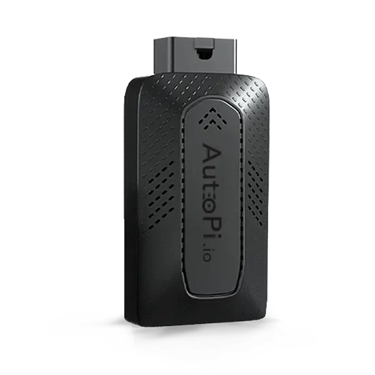
The AutoPi TMU CM4 comes with an integrated 40 pin header (1.27mm pitch). It is possible to use the header to design HAT (Hardware Attached on Top) boards that greatly extends the functionality of the device. The image below shows the placement of the HAT on the board. It has been designed, so that a new HAT can fit into the casing.
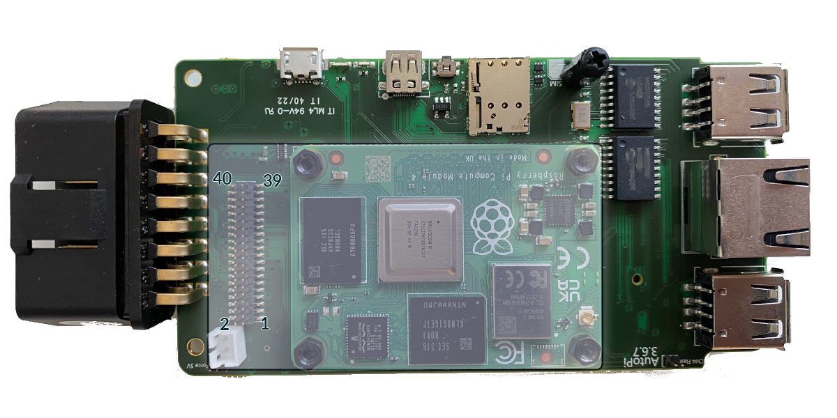
HAT Component Parts
| Type | Manufacturer | Part Number | Datasheet | Comments |
|---|---|---|---|---|
| Male | Greenconn | GPEC209-2002B009C1BF | Datasheet | Alternative manufacturer available |
| Female | Amphenol ICC (FCI) | 20021321-00040C1LF | Datasheet | Alternative manufacturer available |
Pinout
The following table is an explanation of each pinout. The type describes the usage of the pin as defined in the RP2040 firmware:
| Pin | Name | Description | Type | Comments |
|---|---|---|---|---|
| 1 | HS_CAN_HIGH / OBD_PIN_6 | Connection to CAN0 High line and directly to OBD pin | Bi-directional | |
| 2 | HS_CAN_LOW / OBD_PIN_14 | Connection to CAN0 Low line and directly to OBD pin | Bi-directional | |
| 3 | MS_CAN_HIGH / OBD_PIN_3 | Connection to CAN1 High line and directly to OBD pin | Bi-directional | |
| 4 | MS_CAN_LOW / OBD_PIN_11 | Connection to CAN1 Low line and directly to OBD pin | Bi-directional | |
| 5 | OBD_PIN_1 | Directly connected to OBD pin | Bi-directional | |
| 6 | OBD_PIN_7 | Directly connected to OBD pin | Bi-directional | |
| 7 | OBD_PIN_15 | Directly connected to OBD pin | Bi-directional | |
| 8 | OBD_PIN_2 | Directly connected to OBD pin | Bi-directional | |
| 9 | OBD_PIN_10 | Directly connected to OBD pin | Bi-directional | |
| 10 | OBD_PIN_8 | Directly connected to OBD pin | Bi-directional | |
| 11 | OBD_PIN_9 | Directly connected to OBD pin | Bi-directional | |
| 12 | OBD_PIN_12 | Directly connected to OBD pin | Bi-directional | |
| 13 | OBD_PIN_13 | Directly connected to OBD pin | Bi-directional | |
| 14 | GND | Ground | PWR | |
| 15 | 12V_CAR / OBD_PIN_16 | Connection to 12V supply from the car on OBD pin 16 | PWR | |
| 16 | RP2040_GPIO27 | Connection to RP2040 SPM on GPIO27 | Output | 3.3V Level - See RPI2040 datasheet for details |
| 17 | 5V_EXT | Controlable 5V supply | PWR | Maximum current rating 500mA |
| 18 | 3V3_EXT | Controlable 3.3V supply | PWR | Maximum current rating 500mA |
| 19 | DOIP_ACT | Connection to RP2040 SPM on DoIP activate pin | Output | |
| 20 | RPI_GPIO23 | Raspberry Pi CM4 GPIO23 | Bi-directional | 3.3V Level - See CM4 datasheet for details |
| 21 | RPI_GPIO24 | Raspberry Pi CM4 GPIO24 | Bi-directional | 3.3V Level - See CM4 datasheet for details |
| 22 | RPI_GPIO27 | Raspberry Pi CM4 GPIO27 | Bi-directional | 3.3V Level - See CM4 datasheet for details |
| 23 | GND | Ground | PWR | |
| 24 | GND | Ground | PWR | |
| 25 | 5V | 5V Supply | PWR | Maximum current rating 500mA |
| 26 | 3V3 | 3.3V Supply | PWR | Maximum current rating 500mA |
| 27 | ETH_TD0- | Ethernet Data pin TD0- | Bi-directional | |
| 28 | ETH_TD0+ | Ethernet Data pin TD0+ | Bi-directional | |
| 29 | ETH_TD1- | Ethernet Data pin TD1- | Bi-directional | |
| 30 | ETH_TD1+ | Ethernet Data pin TD1+ | Bi-directional | |
| 31 | RPI_PWR | CM4 power status pin | Output | 3.3V Level - See CM4 datasheet for details |
| 32 | RP2040_GPIO17 | Connection to RP2040 SPM on GPIO17 | Input | When high the CM4 will wake - 3.3V Level - See RPI2040 datasheet for details |
| 33 | RP2040_GPIO28 | Connection to RP2040 SPM on GPIO28 | Output | 3.3V Level - See RPI2040 datasheet for details |
| 34 | USB_DP_EXT | USB4 D+ Data line - HAT USB | Bi-directional | |
| 35 | USB_DM_EXT | USB4 D- Data line - HAT USB | Bi-directional | |
| 36 | RPI_GPIO22 | Raspberry Pi CM4 GPIO22 | Bi-directional | 3.3V Level - See CM4 datasheet for details |
| 37 | RPI_ID_SD | Raspberry Pi CM4 ID_SD | Bi-directional | 3.3V Level - See CM4 datasheet for details |
| 38 | RPI_ID_SC | Raspberry Pi CM4 ID_SC | Bi-directional | 3.3V Level - See CM4 datasheet for details |
| 39 | I2C1_SDA | I2C1 Data line | Bi-directional | 3.3V Level - See CM4 datasheet for details |
| 40 | I2C1_SCL | I2C1 Clock line | Bi-directional | 3.3V Level - See CM4 datasheet for details |
Example Dimensions
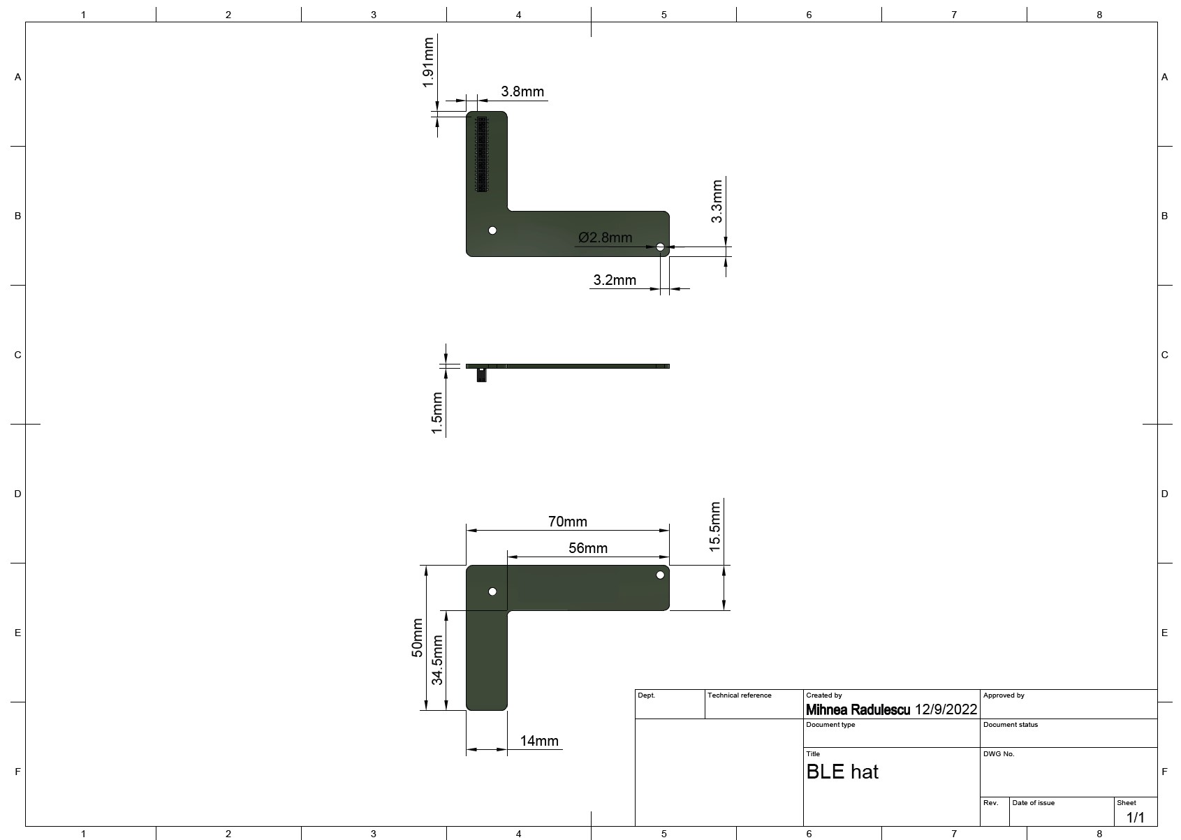
The following picture shows an example layout of the HAT, together with positioning of the female connector. This specific HAT is designed to go around the CM4 board:
 Buy AutoPi device
 Compare all AutoPi devices