Keyfob HAT Pinout
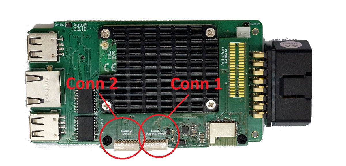
The keyless keyfob extension HAT enables two new ports on the AutoPi device. These can be seen here during the install:
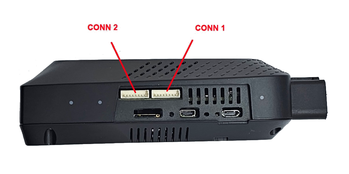
After assembly of the device, the ports can be seen from the picture below:
Pinout Conn 1 - HAT interface
Connection 1 on the Keyfob HAT is controlled locally on the keyfob extension board.
The pinout for this connector is:
| Pin No. | Wire Color | Name | Description | Comments |
|---|---|---|---|---|
| 1 | Red | Vcc3v3_switched | Controllable 3.3V power supply | Controlled by the HAT's onboard MCU |
| 2 | Black | GND | Internal ground | |
| 3 | Yellow | Vcc5v_switched | Controllable 5V power supply | Controlled by the HAT's onboard MCU |
| 4 | Green | DIO9 | Digital input/output | Controlled by the HAT's onboard MCU |
| 5 | Blue | DIO10 | Digital input/output | Controlled by the HAT's onboard MCU |
| 6 | White | DIO3 | Digital input/output | Controlled by the HAT's onboard MCU |
| 7 | Orange | DIO2 | Digital input/output | Controlled by the HAT's onboard MCU |
| 8 | Purple | DIO0 | Digital input/output | Controlled by the HAT's onboard MCU |
Pinout Conn 2 - RPI interface
Connection 2 on the Keyfob HAT is controlled from the AutoPi base board, by the standard AutoPi setup.
The pinout for this connector is:
| Pin No. | Wire Color | Name | Description | Comments |
|---|---|---|---|---|
| 1 | Red | Vcc3v3_switched | Controllable 3.3V power supply | Controlled by the AutoPi base board MCU |
| 2 | Black | GND | Internal ground | |
| 3 | Yellow | Vcc5v_switched | Controllable 5V power supply | Controlled by the AutoPi base board MCU |
| 4 | Green | RPI_ID_SD | Digital input/output | Controlled by the RPi |
| 5 | Blue | RPI_GPIO24 | Digital input/output | Controlled by the RPi |
| 6 | White | RPI_GPIO23 | Digital input/output | Controlled by the RPi |
| 7 | Orange | RPI_GPIO27 | Digital input/output | Controlled by the RPi |
| 8 | Purple | RPI_ID_SC | Digital input/output | Controlled by the RPi |
 Buy AutoPi device
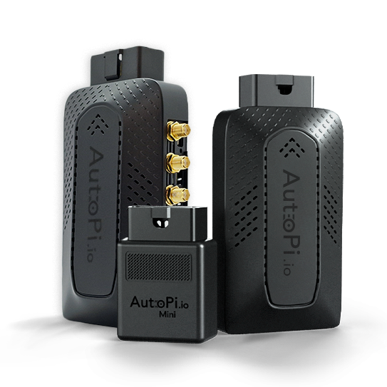 Compare all AutoPi devices
 Contact our sales team