Keyfob Cloud Configuration
Prerequisites before starting:
- The keyfob HAT has been securely installed in your AutoPi TMU CM4 device.
- The keyfob has been correctly soldered to the wires in the extension casing. Ensure that solder joints are solid and free from shorts.
- You have a working AutoPi Cloud account at my.autopi.io with your device already registered.
- Your device is powered, connected to the internet, and synchronized with the AutoPi Cloud.
Step-by-Step Guide
Step 1 – Hardware Connection
Begin by connecting the keyfob casing to the correct port on your AutoPi device. The keyfob must always be connected to CONN2, as shown below:
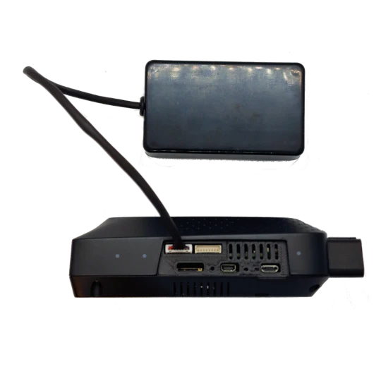
Make sure that the red wire (power) is connected to Vcc3v3_switched. This is critical, as the keyfob is designed to operate on a 3.3V switched power source. Supplying the wrong voltage, or connecting to a continuous supply, can damage the HAT or prevent correct operation.
Check all wiring carefully:
- Red wire →
Vcc3v3_switched(power) - Black wire → GND
- Signal wires → Corresponding button outputs
Proper cable management is also recommended to avoid strain or accidental disconnection inside the extension casing.
Step 2 – Access Cloud Settings
Next, configure the keyfob through the AutoPi Cloud platform.
- Log in at my.autopi.io.
- Navigate to your device and open the Advanced Settings section.
- Locate the Keyfob Tab. If the tab is not visible, contact support@autopi.io to have it enabled.
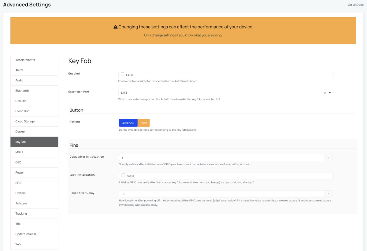
The Keyfob Tab provides the configuration options needed to activate the HAT and define button mappings. Without this configuration, the AutoPi device cannot interpret or forward keyfob button actions to your vehicle.
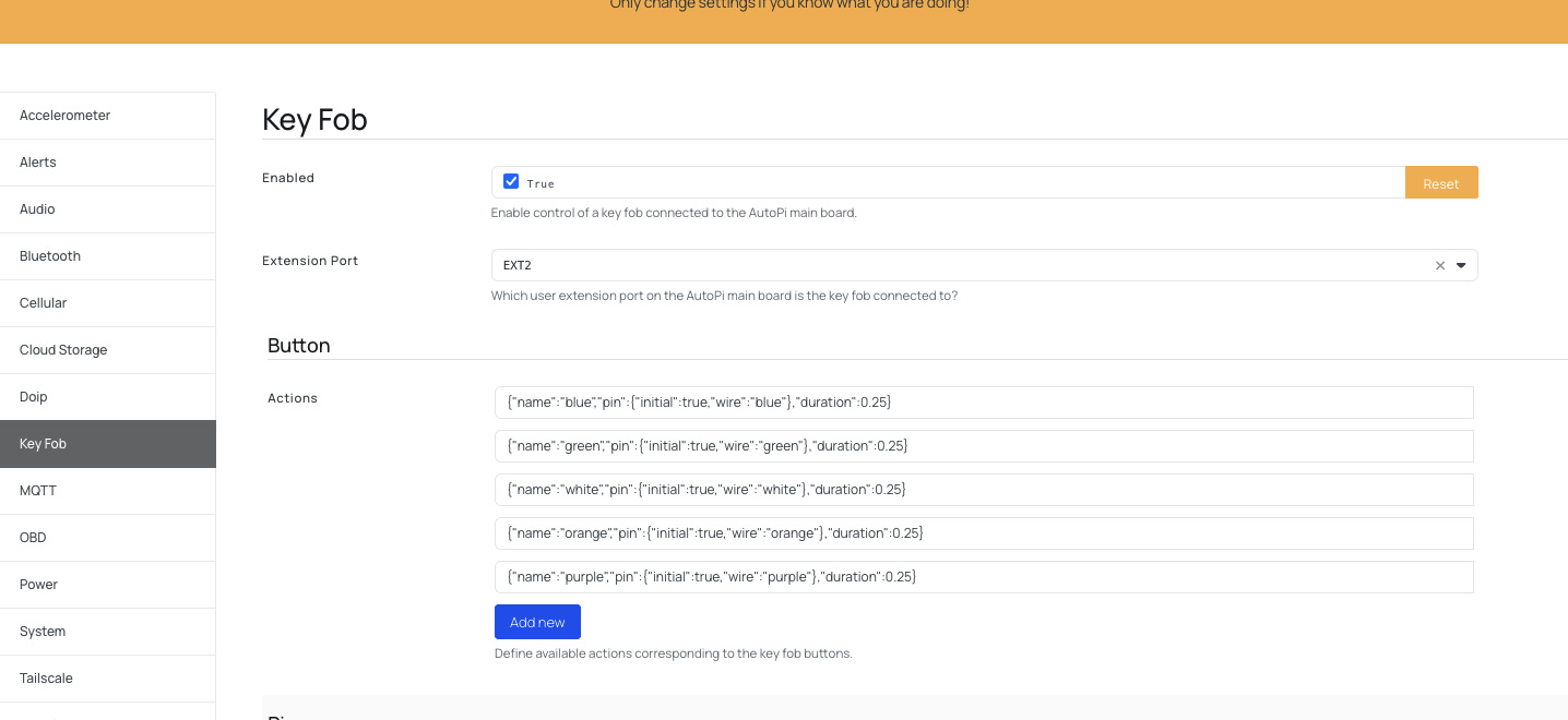
Step 3 – Enable and Configure the Keyfob
Once inside the Keyfob Tab:
- Enable the keyfob feature by pressing the Enable button.
- Set EXT2 as the output port. This assigns the communication channel used to interact with the HAT.
After enabling, press the Reset button under the Buttons section. This action will generate a default list of button mappings. These mappings represent the raw signals detected from your soldered wires.
You must now map each signal to the correct button function, depending on how the keyfob has been wired. For example, a button connected to a green wire may correspond to "Lock," while another connected to a yellow wire may represent "Unlock."
Carefully record your configuration so that the same mapping can be reused later if the device is reset or updated. It is good practice to name buttons clearly, using functional terms such as lock, unlock, trunk, or lights.
Step 4 – Power Up the Keyfob
Before the keyfob can be used, you must explicitly power it on. The keyfob HAT does not receive constant power to prevent unnecessary drain on the device.
- Run the
keyfob.powercommand from the AutoPi Cloud. - Verify that the device is online and has a stable internet connection.
- Open the Live Terminal to interact with the device in real time.
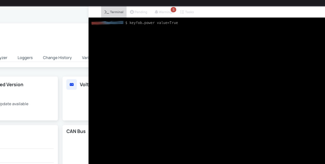
If power is not enabled, none of the keyfob actions will execute. You may also configure power to be enabled automatically on startup if frequent use is required.
Step 5 – Lock and Unlock the Vehicle
With power enabled and buttons mapped, you can now use the keyfob commands.
The main command is keyfob.action. The argument you supply to this command must match the button name you configured in the Keyfob Tab.
For example, if you created a button named unlock, the following command will trigger that function and send the corresponding signal to your vehicle’s central locking system:
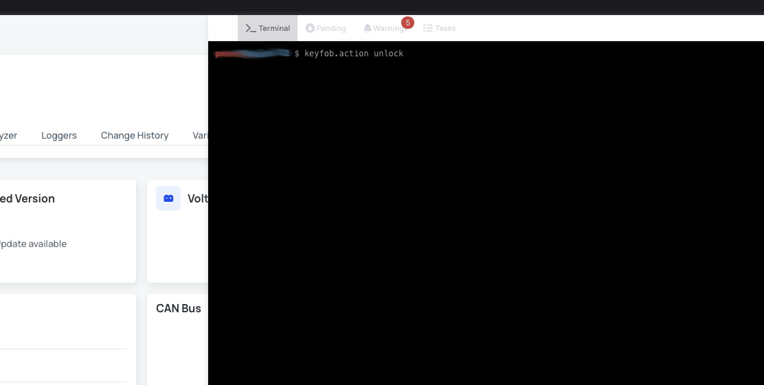
Typical actions include:
- Unlock – Open vehicle doors.
- Lock – Secure vehicle doors.
- Trunk – Release trunk or rear hatch.
- Lights – Flash headlights or activate hazard lights.
Each action depends on how the wires have been soldered to your original keyfob PCB. Always verify functionality in a safe environment before regular use.
Best Practices
To ensure reliable operation and safety:
- Use consistent naming for buttons. Avoid spaces and special characters.
- Document the wire colors and functions in your project notes.
- Test each button individually before finalizing installation.
- Consider heat-shrink tubing around soldered joints for extra durability.
- If the vehicle does not respond, check the wiring orientation and verify that the AutoPi Cloud shows the device as online.
Troubleshooting and Support
If you experience issues:
- Verify that CONN2 is used for the connection.
- Confirm that
Vcc3v3_switchedis supplying power to the keyfob. - Recheck soldering to ensure solid electrical connections.
- Confirm that the Keyfob Tab is visible and enabled in the AutoPi Cloud.
- Run
keyfob.poweragain to confirm that the HAT is active.
If the problem persists, contact support@autopi.io or reach out to your assigned sales representative. Provide details such as your device ID, wiring layout, and button configuration for faster resolution.
 Buy AutoPi device
 Compare all AutoPi devices
 Contact our sales team