OBD Connector Pinout
This guide is applicable to the following device / devices: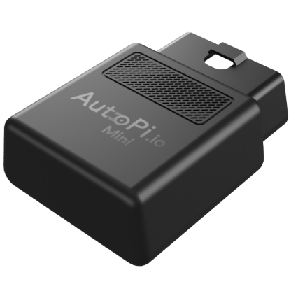
Mini
Overview
The OBD-II (On-Board Diagnostics, revision 2) connector is the standard diagnostic port used in all modern vehicles. The AutoPi Mini connects to your vehicle through this 16-pin connector, allowing you to read vehicle data, monitor diagnostics, and access engine parameters in real-time.
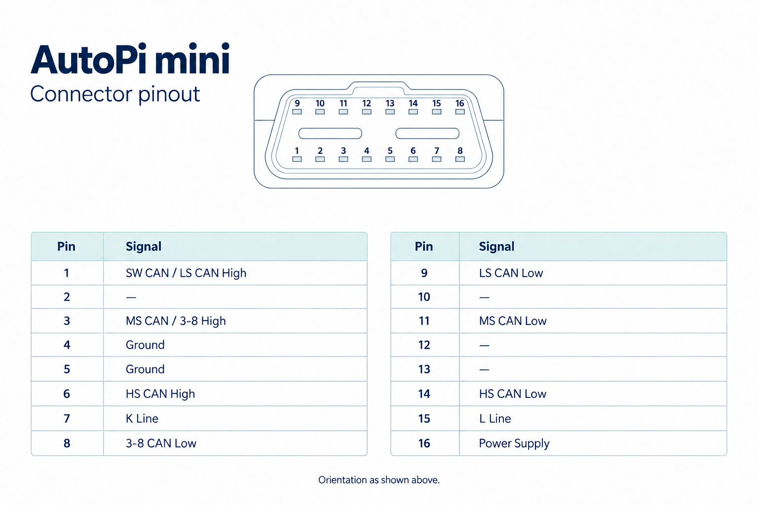
This guide provides the pinout configuration for the OBD-II connector on the AutoPi Mini device, helping you understand the pin layout and best connection practices.
Connector Layout
Connection Best Practices
- Ensure a secure connection to avoid intermittent data loss
- The connector should click firmly into place
- Power cycles are not needed when plugging in the device
- The AutoPi Mini powers on automatically when connected to a vehicle with the ignition in the ON or ACC position
- Verify no bent pins before inserting the connector
Vehicle Communication Protocols
The AutoPi Mini automatically detects and communicates using the protocol supported by your vehicle:
- CAN Bus (ISO 15765-4): Preferred modern standard for most vehicles manufactured after 2008
- ISO 9141-2: Older protocol still used by some vehicles
- KWP2000: Keyword Protocol 2000, alternative to ISO 9141-2
- J1850-PWM: Used in some Ford and GM vehicles
The device intelligently handles protocol switching based on your vehicle's capabilities.
 Shop AutoPi devices
 Compare devices
 Contact sales
 Contact support