Connection Overview
Connectivity
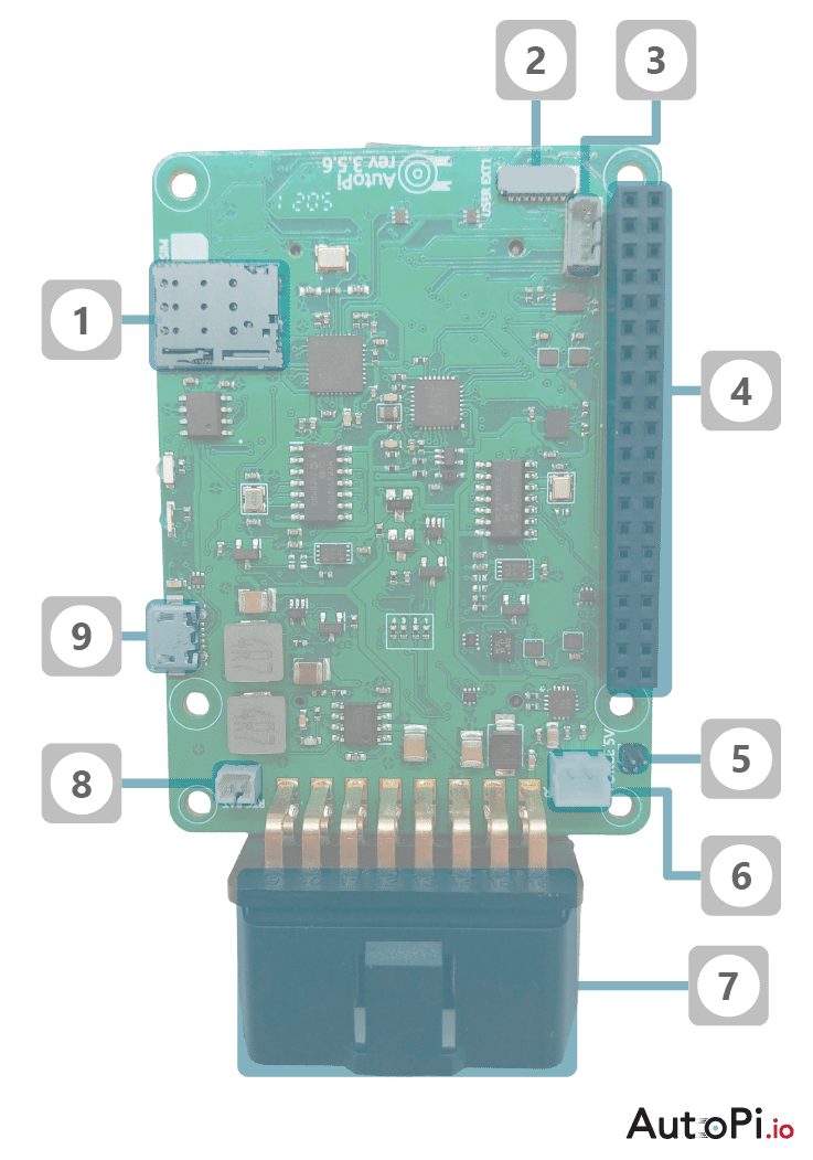
Front Side
This diagram shows the 3.5 CAN-FD generation frontside connections possibilities
- Sim card slot
- USER EXT 1
- ETH CONN
- GPIO pins for RPi and external connections
- GPIO Jumper to always force 5V on the RPi
- JST connector for external speaker
- OBD-II connector to the vehicle
- RTC battery connector
- Micro USB connectors for external use
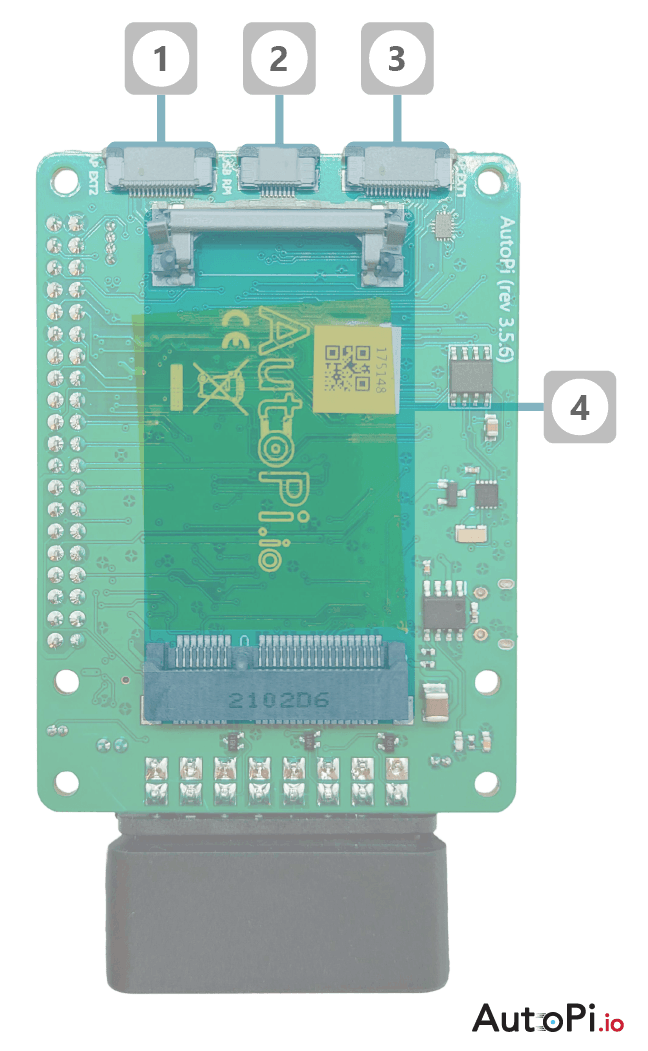
Back Side
This diagram shows the 3.5 CAN-FD generation backside connections possibilities
- AP EXT 2 - BLE module connector
- Upstream USB connector to RPi
- AP EXT 1 - OBD2 pass through connector
- Modem slot
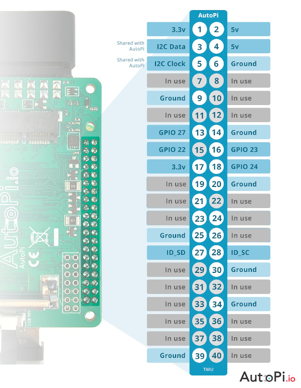
Pinout
GPIO Pins
This image is an overview of the GPIO pinout of the 3.5 CAN-FD generation AutoPi.
Pins marked with "in use" cannot be used for anything else. This will interrupt the functionality of the AutoPi. This I2C bus is used by the AutoPi, but can be shared with other devices.
All other pins are free and their functionality follows that of the Raspberry Pi.
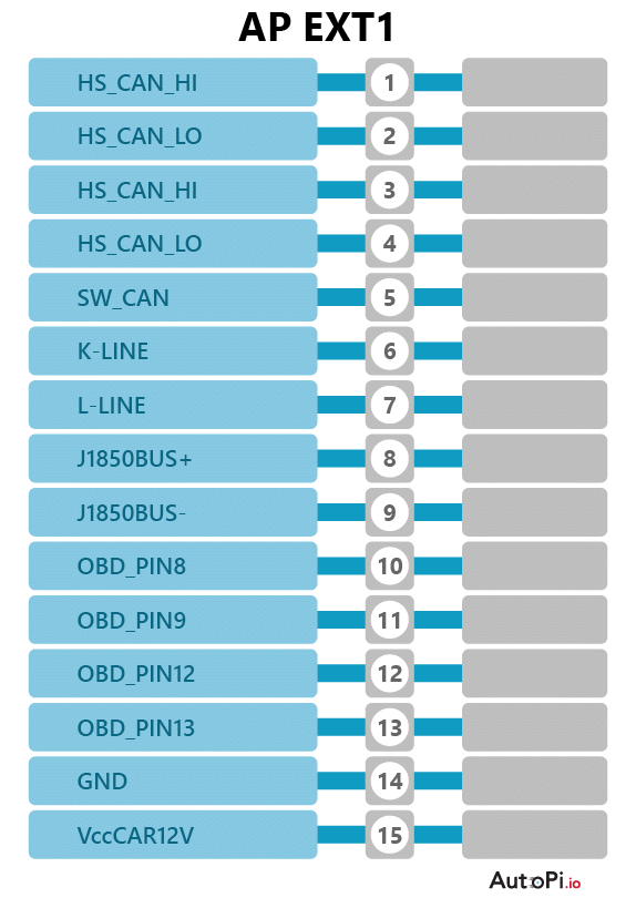
AutoPi Extension Port 1
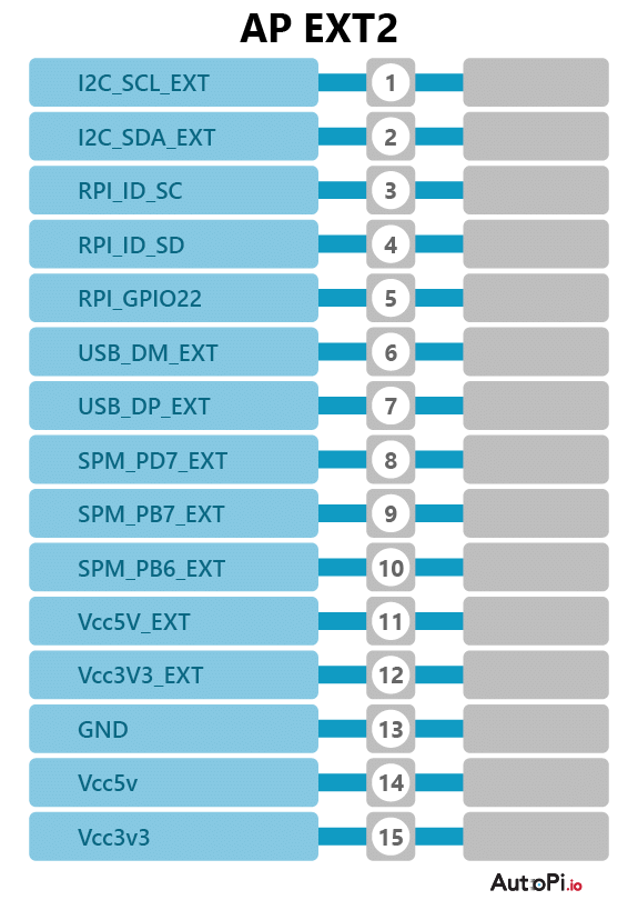
AutoPi Extension Port 2
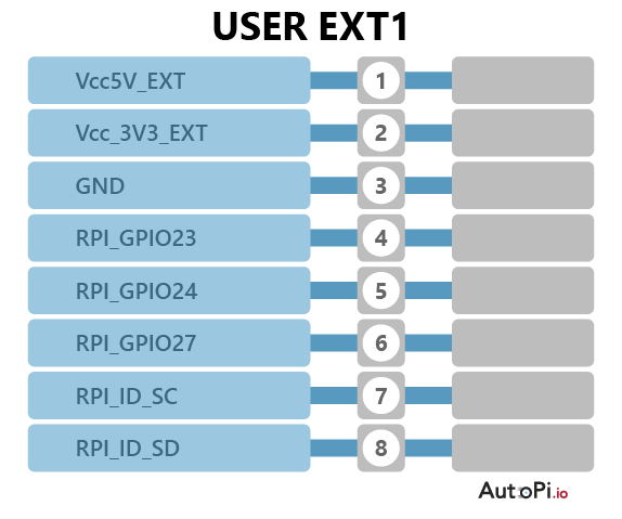
User Extension Port 1
The power to the extension ports can be controlled using the following commands:
spm.query ext_pins [high|low|toggle]=ext_sw_3v3
spm.query ext_pins [high|low|toggle]=ext_sw_5v
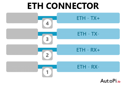
Ethernet Connection Port
 Buy AutoPi device
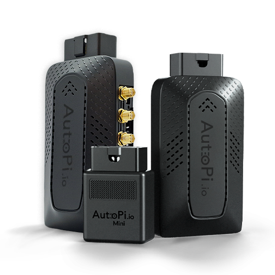 Compare all AutoPi devices
 Contact our sales team